MT5000-0200-1 Rev f (10-2010) DCN0528 28
Linearization Output Units
Level Flow Volume
inches gallons cubic yards cubit ft/sec cubic meters/sec liters/sec
feet liters cubic feet cubic ft/min cubic meters/min liters/min
millimeters imperial gallons cubic inches cubic ft/hr cubic meters/hr liters/hr
centimeters cubic meters liquid barrels cubic ft/day cubic meters/day million liters/day
meters barrels hectoliters gallons/sec barrels/sec imperial gallons/sec
percent (%) bushels gallon/min barrels/min imperial gallons/min
gallons/hr barrels/hr imperial gallons/hr
gallons/day barrels/day imperial gallons/day
million gallons/day
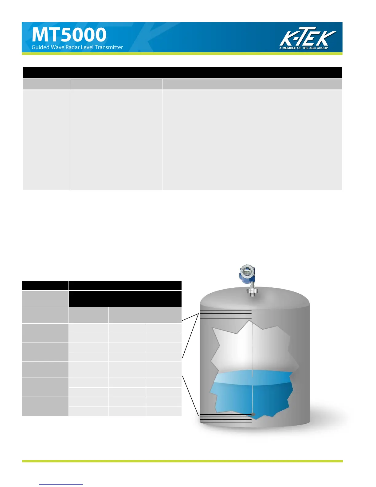
LINEARIZATION for LEVEL
Table 2
Due to the nature of the microwave energy and the physics involved in the measurement of the MT5000, measure-
ments return signals on the top and bottom end of the probe may be non-linear. The degree of non-linearity will de-
pend upon the dielectric of the material being measured, the configuration of the probe, and the proximity of the ma-
terial to the ends of the probe. A typical table setup for measurement linearity will only contain a few Output Points.
Points not used will be left set to 0.00. Below is an example of Linearization set up for Measurement Linearity.
SETTINGS
LIN OUTPUT
Level
LINEARIZATION TABLE
LIN UNITS
inches
MEASURED
LEVEL
OUTPUT POINT
LIN MINIMUM
00.00
0.25” 01 1.00”
1.50” 02 2.00”
LIN MAXIMUM
48.00
2.75” 03 3.00”
3.88” 04 4.00”
LIN MODE
Auto
NOT USED 05 thru 16 0.00”
PROBE LENGTH
51.00
43.88” 17 44.00”
44.75” 18 45.00”
NOZZLE HEIGHT
3.00 inches
45.50” 19 46.00”
46.25” 20 47.00”