MT5000-0200-1 Rev f (10-2010) DCN0528 7
The MT5000 single rod and cable probe can be cut to length prior to installation. If shortening of the probe is neces-
sary, cut the rod or cable to the desired length using a hacksaw.
Shortening of coaxial probes in the field is not recommended.
The centering disc or weight at the end of the probe must be reattached for proper operation.
The Probe Length parameter in the Basic Setup menu will need to be adjusted for the new probe length.
3.2 Shortening of Probe
Electrical connection to the MT5000 should approach the transmitter head from below the conduit opening to provide
a drain for moisture. Install conduit to ½‖ NPT port and run 18 gauge twisted, shielded pair to housing. Refer to Sec-
tion 4 wiring diagram ELE1015 for typical loop wiring diagram and to ELE1014 for instructions applicable to intrinsic
safety installation.
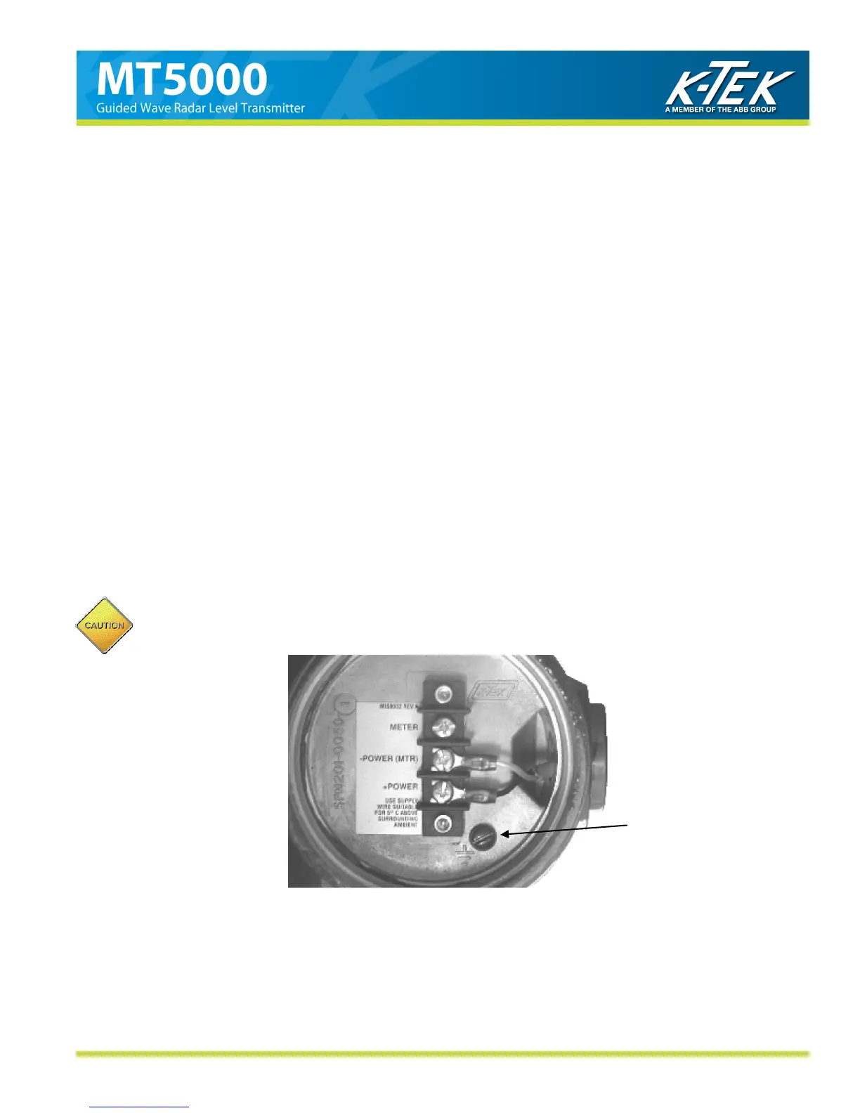
Apply loop power to the transmitter as follows:
Terminal Block + 14 VDC minimum to 36 VDC Maximum
Terminal Block - To control System Input
Ground Screw GROUND
Note: The ―+Meter‖ and ―-Meter‖ terminals are available to hook up a mA meter to monitor loop current, without
breaking the loop.
3.3. Electrical Installation
The housing cover can only be removed when the unit is installed in a non-hazardous area, when in-
stalled with intrinsic safety barrier, or when power is removed from the transmitter.
Ground
Screw