2. Loosely fasten the connection cable to the door beams using cable ties.
3. For shielding, strip the Ethernet data cable at the position of the shield clamp up to the wire mesh (approx. 20mm)
and fix it with cable ties.
4. Open and close the door completely to check that the connection cable is not subject to tensile or compressive
forces.
5. Check that the connecting cable is fitted securely.
6. Tighten the cable fittings [[ W_29 / 4 Nm].
ð Connect additional signal cables.
Connecting the device to the network
↻ Connect the Ethernet cable to the device.
1. Connect the Ethernet cable to the network or a computer.
2. Configure the Ethernet settings and the web server in the Settings menu.
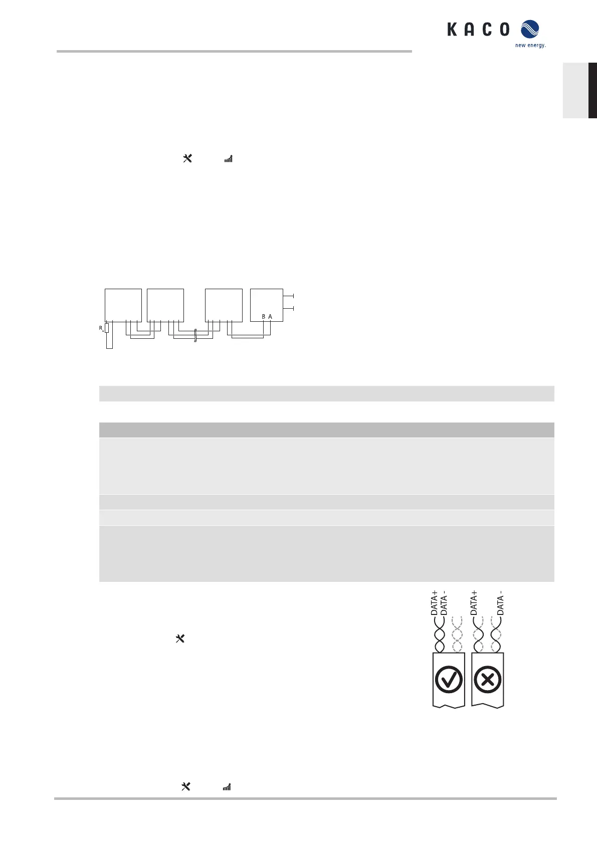
7.6.4 Connecting the RS485 Bus
A B GND A B GND A B GND A B GND A B GND A B GND
Fig.35: RS485 interface wiring diagram
1 Inverter, terminal unit 4 Communication
2 Inverter 5 Power supply
3 Data monitoring unit
Properties of the RS485 data line
Maximum length of the RS485 bus line Max. 1200 m
This length can be reached only under optimum condi-
tions. Cable lengths exceeding 500 m generally require
a repeater or a hub.
Maximum number of connected bus devices 99devices + 1datamonitoringunit
Data line Twisted, shielded.
Recommendation Li2YCYv (twisted pair) black for laying cable outside
and in the ground, 2 x 2 x 0.5 mm²
Li2YCY (twisted pair) grey for dry and damp indoor
spaces, 2 x 2 x 0.5 mm²
↻ To prevent interference during data transmission:
- Observe the wire pairing when connecting DATA+ and DATA-.
Do not lay RS485 bus lines in the vicinity of live DC/AC cables.
1. Loosen the cable fitting [ W_20]
2. Thread the connection cables through the cable fitting.
3. Open and close the door completely to check that the connection cable is not
subject to tensile or compressive forces.
4. Connect the connection cable to the corresponding connection terminals.
5. The following must be connected to all inverters and to the data monitor unit in
the same way:
- Wire A (-) to wire A (-) and wire B (+) to wire B (+)
- GND to GND
6. Secure cable ties.
7. Tighten the cable fittings [ W_20 / 1.5 Nm]
Fig.36: Assignment of twisted-pair
wires
Manual Installation | 7
KACO blueplanet 3.0 TL3 KACO blueplanet 4.0 TL3 KACO blueplanet 5.0 TL3 KACO blueplanet 6.5 TL3 KACO
blueplanet 7.5 TL3 KACO blueplanet 8.6 TL3 KACO blueplanet 9.0 TL3 KACO blueplanet 10.0 TL3
Page 29
EN

 Loading...


