Country-
spec. Set-
tings
Men
u
level
Display/
Setting
Action in this menu/meaning
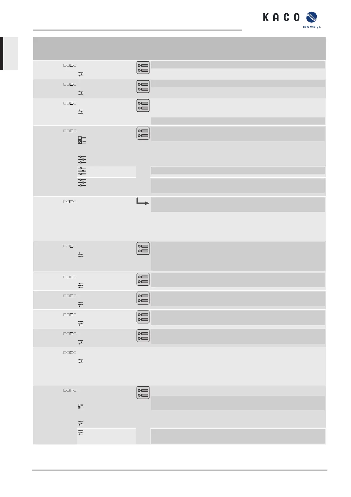
Lock-In voltage
23V – 287V
F Set the voltage above which control is activated.
Lock-Out voltage
23V – 287V
F Set the voltage below which control is deactivated.
Number of nodes
2 - 10
NOTE:The maximum number of configurable nodes depends
on the selected grid type.
F Specify the number of nodes for the cos ϕ /(p/pn).
1st node … 10th node
Voltage | Reactive
power | Excitation
0-100%
F Power factor for 1st ,10th ... node as a percentage of the maximum
power.
1 – 0.3
F Specify the NOTE:cos ϕ of the node.
Over-excited | un-
der-excited
F If a reactive power not equal to 1 is selected: Select the type of
phase shift.
Q(U) 10 Samples F Open the menu: Press the Right arrow button or Enter
button.
NOTE:More detailed information about the procedure can be
found at:
[See section10.1}Page55]
Settling time
1s – 120 s
F Set the settling time in the event of an abrupt change in the reactive
power target value (e.g. caused by a voltage jump). The transient re-
sponse corresponds to a first-order filter (PT-1) with settling time =
5Tau.
Lock-In power
0 – 100% S
max
F Set the active power as % of rated power above which control is ac-
tivated.
Lock-Out power
0-100% S
max
F Set the active power as % of rated power below which control is de-
activated.
Lock-in time
0 s – 60 s
F Set the length of time that the active power must remain below the
lock-in power level before control is activated.
Lock-out time
0 s – 60 s
F Set the length of time that the active power must remain below the
lock-out power level before control is deactivated.
Downtime
0-10000 [ms]
If the voltage switches from a characteristic curve section with Q=0 to a
characteristic curve section with Q≠0 under active control, then the re-
active power setting process is delayed by the set dead time. Once the
dead time has expired, the control circuit is no longer subject to a delay
and the set transient time determines the transient behaviour.
Rise Outg. grad. & Fall.
Outg. grad.
increasing | decreas-
ing
1 %-60000 %/min
F Maximum change in the reactive power %S
lim
/min in the event of a
change to over-excited mode.
1 %-60000 %/min F Maximum change in the reactive power %S
lim
/min in the event of a
change to under-excited mode.
9 | Configuration and operation Manual
KACO blueplanet 3.0 TL3 KACO blueplanet 4.0 TL3 KACO blueplanet 5.0 TL3 KACO blueplanet 6.5 TL3 KACO
blueplanet 7.5 TL3 KACO blueplanet 8.6 TL3 KACO blueplanet 9.0 TL3 KACO blueplanet 10.0 TL3
Page 44
EN
 Loading...


