Country-
spec. Set-
tings
Men
u
level
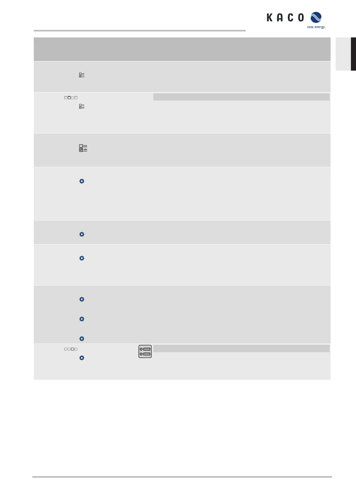
Display/
Setting
Action in this menu/meaning
Reference power
Actual power |
Nominal power
Specifies the power reference for the characteristic curve. 100% here
corresponds to the nominal power or the actual power at the time the
function was activated, the time when the voltage passes the con-
figured node.
Evaluated voltage
Maximum phase
voltage | Positive
phase sequence
voltage
F Select the voltage to be rated.
Specifies which voltage is evaluated in a three-phase system.
Hysteresis mode
Off | On
Off: In non-hysteresis mode, the active power is increased immediately
with dropping voltage.
On: In hysteresis mode, the power is not increased with dropping
voltage. .
Deactivation gradient
1 - 65,534 [% / min]
If the available power is above the actual output at the time of deactiva-
tion, the power increase back to the maximum power is limited. The
limitation is implemented by an absolute power limitation that in-
creases with a continuous gradient up to the maximum power. The ac-
tual power of the inverter may vary freely below this limit due to a pos-
sible fluctuation in the available power or the target value, but at no
time increases above the absolute power limit.
Deactivation time
0 – 60000000 [ms]
Only evaluated with activated hysteresis mode: Monitoring time during
which the voltage must remain below the lowest configured node be-
fore the function is deactivated.
Settling time
100 – 1,200,000 [ms]
Determines the dynamic behaviour in the event of a change in the act-
ive power set value. With a voltage change, the active power is changed
according to a PT-1 characteristic curve with a settling time of 5Tau.
Note: The settling time is overlaid with the increasing and decreasing
gradient.
Number of nodes
2 - 5
Power
0.0 -100.0 [%]
Voltage
0.0 -126.0 [%]
Up to five nodes for voltage [V] and power [% Pref] are configurable.
The power value of the first and last value pair is also used as the max-
imum or minimum active power value that is valid across the limits of
the characteristic curve.
Active curve
1 - 5
F Select active curve.
NOTE:Up to 5 characteristic curves can be configured inde-
pendently and one of them can be activated for regulation
each time.
10.2.3 P(f)
Adjusting the active power P(f) in the event of overfrequency
Feed-in inverters must assist with frequency stability in the grid. If the grid frequency leaves the normal toler-
ance range (e.g. ±200mHz), then the grid will be in a critical state. In the event of overfrequency, there is a
generation surplus, in the event of underfrequency, there is a generation deficit.
PV systems must adapt their feed-in power relative to the frequency deviation. In the event of overfrequency,
the power adjustment is determined by a maximum feed-in limit. The actual power of the inverter may vary
freely below this limit due to a possible fluctuation in the available power or the target value, but at no time in-
creases above the absolute power limit.
Manual Specifications | 10
KACO blueplanet 3.0 TL3 KACO blueplanet 4.0 TL3 KACO blueplanet 5.0 TL3 KACO blueplanet 6.5 TL3 KACO
blueplanet 7.5 TL3 KACO blueplanet 8.6 TL3 KACO blueplanet 9.0 TL3 KACO blueplanet 10.0 TL3
Page 61
EN
 Loading...


