Parameters Setting Refer-
ence
Description
Power Limitation
[WMaxLimPct]
0 – 100 [%] Set power limitation to a specific % value.
Timeout
[WMaxLimPct_RvrtTm
s]
0 – 1000 [s] Sets the time after which the inverter, if it
does not receive a new power limit, will
cancel it.
If the Timeout to 0 seconds, the transmit-
ted power limit is permanently maintained,
even in the event of a communication fail-
ure.
Note: When the unit is restarted, the
timeout is reset to the set fallback time.
10.2.2 Voltage-dependent power reduction P(U)
If it is not possible to compensate adequately for increase in voltage in the upstream distribution network by
intake on reactive power, it may be necessary to curtail the active power. In this case, P(U) control is available
for making optimum use of the capacity of the upstream grid.
P(U) control reduces the active power that is fed in as a function of the grid voltage using a prescribed charac-
teristic curve as a basis. P(U) control is implemented as an absolute power limit. The actual power of the in-
verter may vary freely below this limit due to a possible fluctuation in the available power or the target value,
but at no time increases above the absolute power limit.
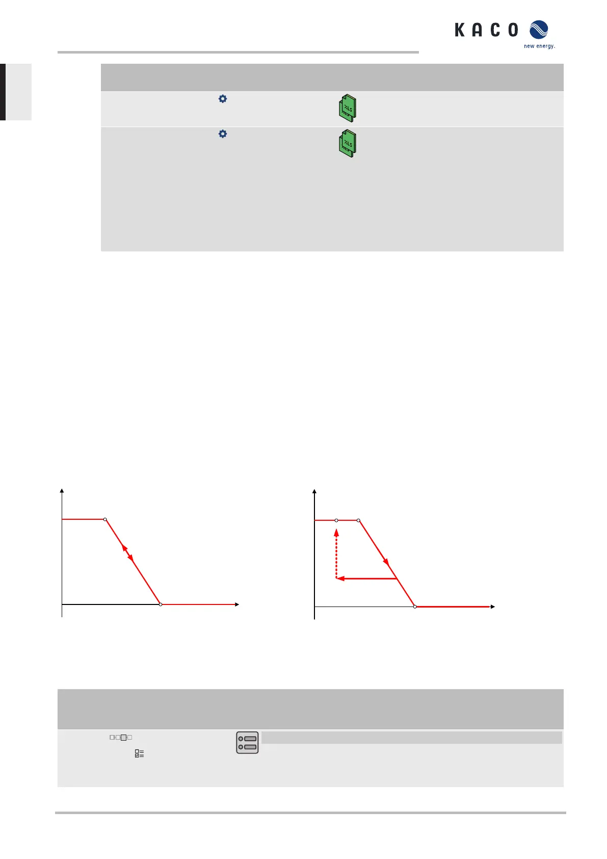
[See figure 45 [}Page60] and [See figure 46 [}Page60] are two examples of configuration. In figure 1
without hysteresis, the function is activated as soon as the voltage exceeds the configured voltage of data point
1 (dp1). The power limit follows the characteristic curve, a straight line between dp1 and dp2. The function is
deactivated as soon as the voltage falls below dp1. In [See figure 46 [}Page60], the function is activated as
soon as the voltage exceeds the configured voltage of dp2. In this case, dp1 does not result in activation of the
function because the power limit remains at 100%. The power limit follows the characteristic curve, a straight
line between dp2 and dp3. However, because hysteresis is activated, the power limit is not increased when the
voltage drops. The function is deactivated as soon as the voltage falls below dp1.
Voltage
P / Pref
dp 1
dp 2
Fig.45: Example characteristic curve without hysteresis
P / Pref
dp 1
dp 3
dp 2
Voltage
Fig.46: Example characteristic curve with hysteresis and a deactiv-
ation threshold below the activation threshold
10.2.2.1 Parameters for P(U)
Country-
spec. Set-
tings
Men
u
level
Display/
Setting
Action in this menu/meaning
P(U) operation mode
Off | On
F Activate the control process.
Off: Deactivates dynamic grid support using dynamic reactive current.
Dynamic grid support remains active on account of immunity to inter-
ference.
10 | Specifications Manual
KACO blueplanet 3.0 TL3 KACO blueplanet 4.0 TL3 KACO blueplanet 5.0 TL3 KACO blueplanet 6.5 TL3 KACO
blueplanet 7.5 TL3 KACO blueplanet 8.6 TL3 KACO blueplanet 9.0 TL3 KACO blueplanet 10.0 TL3
Page 60
EN
 Loading...


