25
Service and Repair Manual
Model 900/950/990
1. Fit the two terminal housings (131).
2. Fit the two brush holders (130) into the brush
holder housing (132). Fit the brush holder
alignment service tool through the brush holders.
3. Fit the two brush holder retaining straps (114)
and four retaining screws (113).
Assembling
the brush
holder (All
models)
132
131
130
129
114
113
1. Fit the pressure ring (134), the two waved washers
(133) and the assembled brush housing. Feed field
leads through holes in brush holder housing.
Note: The brush housing is correctly located when
the housing is flush with the top of the motor
case, when light pressure is applied.
2. Connect the two field connections to the brush
terminals (130) and tighten the two terminal
screws (129).
3. Fix on the top bearing shroud (112). Lubricate and
the fit the top bearing inner ring only (126), using
service tool No. 9170 0232 40.
Assembling
the brush
housing
assembly and
rear
armature
bearing (All
models)
126
112
134
133
129
130
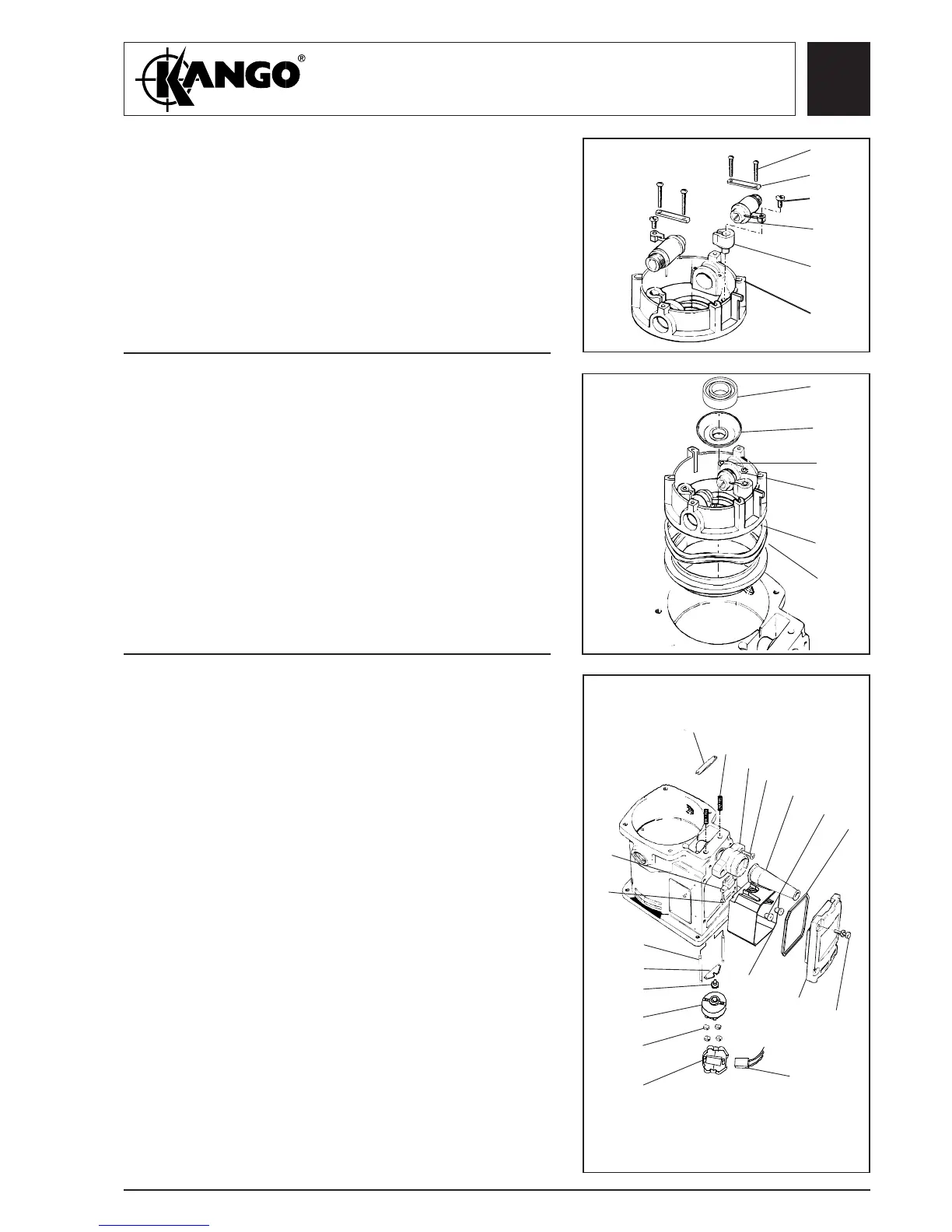
1. Fit the switch box liner (154) and pass the two field
coil switch leads through into the liner. Fit a
grommet (166) over each lead and press the
grommets into the liner apertures.
2. Fit switching pad (165), switch actuator plate (125)
to the two push rods (123) and pass the push rods
through the motor housing into the switch box
opening. Fit the springs (177) over the push rods
and fit the plunger abutment plate (124).
3. Fit the cord guard (169) in the cord guard housing
(167) and pass the power lead through the cord
guard ensuring there is sufficient lead available to
connect to the switch.Fit the switch cup (155), the
four terminal pads (164), the switch (159) and the
switching pad (165).
4. Fit the switch cup (155), the four terminal pads
(164), and condenser (158).Connect the switch
leads, power leads and condensor connections. Fit
the switch (159) and four terminal pads (164) into
the switch cup (164). Fit the assembled switch into
the switch box liner (154). Fit the switch box seal
(160) and switch box cover (163 and secure with
the four screws (162).
Assembling
the switch
(All models)
123
125
165
159
164
155
158
152
169
168
167
177
166
124
162
163
154
160
153
Fig. 25
Fig. 26
Fig. 27