30
Service and Repair Manual
Model 900/950/990
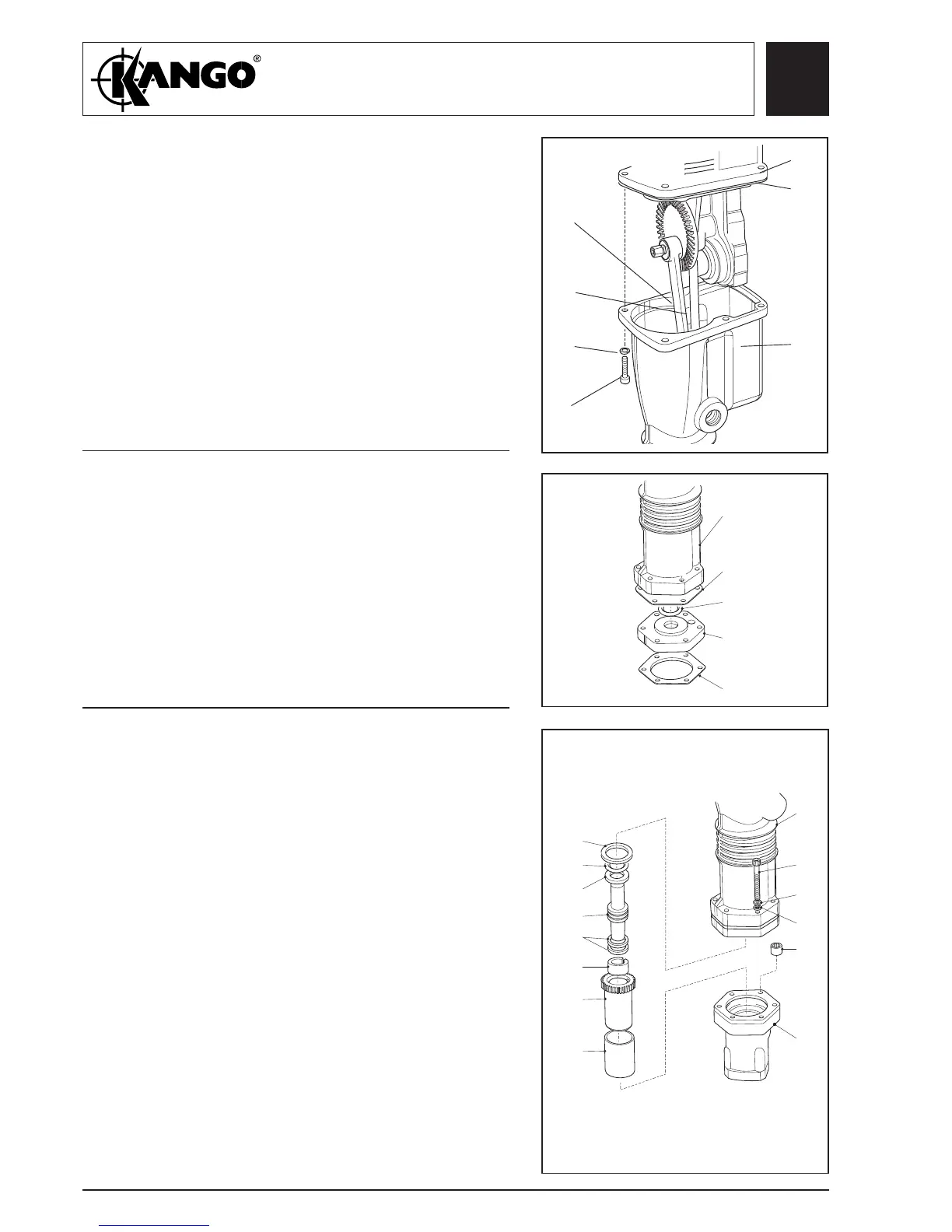
1. Fit the hammer case (346, 228, 428, 528)
vertically in a vice between soft metal jaws.
2. Lightly grease the hammer case gasket (150) and
locate on the hammer case.
3. Fit the assembled motor and gear carrier into the
hammer case. For 950 models ensure the drive
shaft (345) is correctly located.
4. Secure the hammer case using the six screws
(348, 227, 427, 527) and washers (347, 226, 426,
526).
Fitting the
hammer case
(All models,
950 shown)
347
226
426
526
149
150
346
228
428
528
Fitting the
buffer
housing (All
models,
model 950
shown)
1. Press the buffer housing ring (353, 232) into the
groove in the buffer housing (354, 233).
2. Fit the buffer housing gasket (352, 231) to the
hammer casing (346, 228).
3. Fit the buffer housing (354, 208) and buffer
housing gasket (375, 234) to the hammer casing.
4. For 990 only fit spacer (432) and extra gasket
(231, 352, 433) between gasket and buffer
housing.
Assembling
the
transmitter
housing (All
models,
model 950
shown)
1. Place the transmitter housing (359) vertically in a
vice between soft metal jaws. Using service tool,
part no. 917003270, press the drive shaft bearing
(374) into the transmitter housing . Press the
driver bearing (371) into the transmitter housing
(359). (Model 950 only).
2. Insert the junk ring (373, 240), with the flat
surface down, into the driver (372) or anvil
sleeve.
3. Insert the recoil transfer ring (356, 237), rubber
ring (355, 236) into the transmitter housing.
4. Fit the two anvil rings (358, 239) on to the anvil
(357, 238) and insert the anvil into the driver
(372) or anvil sleeve. Insert the anvil and driver
assembly into the transmitter housing (369, 242).
5. Fit the assembled transmitter housing to the
hammer casing and secure with the six screws
(349, 229), spring washers (350, 230).
348
227
427
527
345
(950
ONLY)
305
205
405
505
Fig. 40
Fig. 41
Fig. 42
235
355
236
356
237
357
238
358
239
373
240
371
372
349
229
350
230
351
346
228
374
369
242
439
354
233
375
234
346
228
352
231
353
232