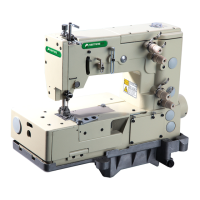
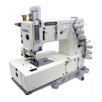
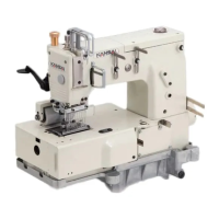
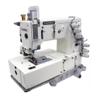
This document is an instruction manual for the Kansai Special VW Series of industrial sewing machines, specifically covering models V7100/D, DE, F, ML, W8100/D, DE, F, C, W8042, W8042-1, V7002-1S, and W8103-1S. It provides detailed guidance on operation, adjustment, and maintenance.
Function Description
The Kansai Special VW Series comprises industrial sewing machines designed for various sewing applications. The manual outlines procedures for setting up the machine, adjusting its components for optimal stitch formation, and performing routine maintenance to ensure longevity and consistent performance. Key functions covered include needle selection and replacement, threading, machine speed control, lubrication, installation, timing of the looper to the needles, adjustment of needle guards, feed dogs, stitch length, spreader, presser foot, and stitch formation elements.
Important Technical Specifications
Needles:
- Schmetz UY128GAS: Available in Nm65 (#09), Nm70 (#10), Nm75 (#11), Nm80 (#12), and Nm90 (#14).
- Organ UY128GAS: Available in #09, #10, #11, #12, and #14.
- Right needle of model-1S series: Schmetz TV7 (Nm75) and Organ TV7 (#11).
- Needles must be installed with the scarf turned to the rear of the machine.
Machine Speed:
- Motor: 3-phase, 2-pole, 400W clutch motor.
- Belt: M type V belt.
- Pulley Rotation: Counterclockwise as seen from the end of the machine pulley.
- Belt Tension: 1-2cm deflection when pressing the finger onto the middle of the belt.
- Maximum and Standard Speeds (SPM - Stitches Per Minute):
- V7100: Max 6000SPM, Std 5500SPM
- W8100: Max 5500SPM, Std 5000SPM
- W8042-1: Max 4500SPM, Std 4000SPM
- W8103-1S: Max 3000SPM, Std 2500SPM
- Motor Pulley Selection Table (Outer Diameter in mm / Machine Speed SPM):
- 60mm: 2500 (50Hz), 2950 (60Hz)
- 70mm: 2900 (50Hz), 3450 (60Hz)
- 80mm: 3300 (50Hz), 3900 (60Hz)
- 90mm: 3700 (50Hz), 4400 (60Hz)
- 100mm: 4100 (50Hz), 4900 (60Hz)
- 110mm: 4500 (50Hz), 5400 (60Hz)
- 120mm: 5000 (50Hz), 5900 (60Hz)
- 130mm: 5300 (50Hz), (6400) (60Hz)
- 140mm: 5800 (50Hz), (6900) (60Hz)
Looper Timing to Needles:
- Looper Angle (V7100, W8100): 3°.
- Looper Height (V7100, W8100): Approximately 1.3mm distance at 25mm from the looper point between the bottom of the looper blade and the extension line from the looper point.
- Needle Height (Distance A from top surface of needle plate to left needle point when needle bar is at top stroke):
- 1/8" (3.2mm): 8.8mm
- 5/32" (4.0mm): 8.2mm
- 3/16" (4.8mm): 7.8mm
- 7/32" (5.6mm): 7.4mm
- 1/4" (6.4mm): 7.8mm (for 2-Needle) / 7.4mm (for 3-Needle)
- W8042: 8.7mm
- W8042-1: 9.5mm
- V7002-1S: 9mm
- W8103-1S: 7.8mm
- Looper Connecting Bar Length (Pitch A):
- V7100, W8100: 100mm
- W8042: 102mm
- W8042-1: 105mm
- Looper Setting Distance (Distance A from looper point to center of right needle):
- 3.2mm (1/8"): 5.0mm
- 4.0mm (5/32"): 4.6mm
- 4.8mm (3/16"): 4.2mm
- 5.6mm (7/32"): 3.7mm
- 6.4mm (1/4"): 3.5mm
- W8042: 4.0mm
- W8042-1: 4.5mm
- Needle/Looper Front-to-Back Relationship:
- Clearance between right needle and looper: 0-0.05mm (looper moving on back side of needles).
- Clearance between left needle and looper: 0.2mm (looper moving on back side of needles).
Needle Guards:
- Rear Needle Guard (Height): Line 'a' of guard even with center of right needle eye when needles are at bottom dead center.
- Rear Needle Guard (Clearance): 0.0-0.05mm between needles and rear guard.
- Rear Needle Guard (-1S models): 0.8mm from right needle point to line 'A' on guard, 0mm clearance between needle and guard.
- Rear Needle Guard (W8042 fixed type): 3mm from line 'A' to needle point when needle bar is at bottom stroke.
- Rear Needle Guard (W8042-1): 1mm from line 'A' to needle point when looper reaches right side of needle, 0mm clearance between needle and guard.
- Front Needle Guard: Align center of right needle's eye with line 'A' on guard when looper reaches center of right needle.
- Front Needle Guard (Clearance): 0.2-0.5mm between needles and front guard.
Feed Dogs & Stitch Length:
- Feed Dog Height: 0.8-1.2mm above top surface of needle plate when feed dogs are at top of stroke.
Spreader:
- Spreader Position (Height): 7-8mm from top surface of needle plate to bottom surface of spreader.
- Spreader Position (Clearance with left needle): 0.5-1mm when thread carrying notch passes left needle.
- Spreader Position (Left end of travel): 5-6.5mm from center of left needle to thread carrying notch.
- Spreader Thread Eyelet (Clearance B and A): 0.5-0.8mm.
- Spreader Thread Eyelet (Right end of travel): Align point (a) of thread carrying notch with center of slot on spreader thread eyelet.
- Spreader Thread Eyelet (Needle bar at bottom stroke): 1mm clearance between spreader thread eyelet B and C. Align eye of C with center line of slot on B.
- Presser Foot Lift (with spreader): 5mm above top surface of needle plate.
- Presser Foot Lift (without spreader): 6mm above top surface of needle plate.
- Needle Thread Eyelet Position: Approximately 16mm from center of eyelet to set screw A.
- Thread Support Position: Centers of eyes on thread eyelet A level with top surface of thread support B, and eyelet A parallel with support B when needle bar is at bottom stroke.
- Spreader Thread Eyelet Position: Approximately 13mm from center of eye of thread eyelet A to part (a) on thread eyelet B when needle bar is at top stroke.
- Looper Thread Take-up Thread Eyelet Position: 6-7mm from top surface of guide plate A to bottom surface of thread guide E.
Usage Features
- Pre-operation Checks: Before starting, ensure pulley cover, safety cover, etc., are secured.
- Safety First: Always turn off the power before adjusting, cleaning, threading, or replacing the needle. Be aware that a clutch motor continues running for a while after being turned off; keep pressing the pedal until it stops.
- Oil Requirement: Never operate the machine without oil in the reservoir.
- Initial Run-in Period: For the first 200 hours (approx. 1 month) of operation, run the machine at 15-20% below the maximum speed to extend machine life. After this period, operate at the standard speed.
- Threading Accuracy: Correct threading is crucial to prevent skip stitching, thread breakage, and uneven stitch formation. The manual provides detailed diagrams for threading different models.
- Adjustments: Most adjustments involve loosening screws, repositioning components, and then tightening the screws. Specific instructions are provided for each adjustment point, often with diagrams and precise measurements.
- Stitch Length Control: Stitch length is adjusted by turning screw B after loosening bolt A with a 9.5mm T wrench. Counterclockwise increases length, clockwise decreases it.
- Differential Feed Ratio: Adjusted by moving nut D up (increase ratio) or down (decrease ratio) after removing rubber plug C and loosening nut D.
- Presser Foot Pressure: Adjusted by turning a knob clockwise to increase pressure. The pressure should be as light as possible while still feeding fabric and producing uniform stitches.
Maintenance Features
- Oil Type: Use Kansai Special's genuine oil (Part No. 28-611).
- Oil Level Check: Fill oil until it reaches the top line (H) on the oil gauge C. After initial lubrication, maintain the oil level between H and L.
- Oil Flow Check: After filling, run the machine to ensure oil splashes from oil pipe outlet B.
- Initial Oil Replacement: Replace the oil after the first 250 hours of operation to extend machine life.
- Oil Replacement Procedure:
- Remove the V belt from the motor pulley.
- Remove the machine from the table.
- Remove screw D to drain the oil (be careful not to stain the V belt).
- Tighten screw D after draining.
- Refill with new oil as per the oiling instructions.
- Filter Element Maintenance: Clean the filter element (E) every six months. If oil flow is insufficient despite proper oil levels, check the filter element. To clean it, remove the oil reservoir.
- Daily Cleaning: At the end of each day, remove the presser foot and needle plate, then clean the slots of the needle plate and the area around the feed dogs.
- Parts List Reference: Refer to the parts list in conjunction with the instruction manual for preventive maintenance.
- Manual Updates: The contents of the instruction manual are subject to change without notice.