Chapter 3 - Connecting your radio
15
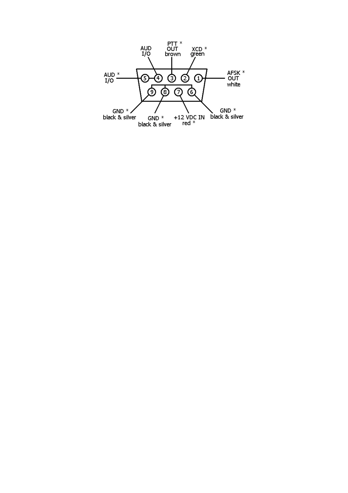
VHF Radio Connector
* Same as 9-pin KPC-2/KPC-2400 connector
The prewired cable assembly with a 9-pin oblong plug (DB-9) attached is for use with the VHF
port. You will need to provide the mic-jack connector for your VHF transceiver and wire the con-
nector to the provided cable.
CAUTION: Check your VHF transceiver manual to correctly wire the corresponding pins of the
transceiver mic-jack.
Pin 1 – AFSK OUT – white lead
This line carries the AFSK tone generated by the KAM to the Audio (microphone) Input line of your
transceiver.
Pin 2 – XCD – green lead
This line may be used to connect the squelch line from your VHF transceiver if desired. This con-
nection will not normally be required, nor used, unless operating an a shared voice channel.
Pin 3 – Push-To-Talk – brown lead
This line controls the PTT line in your transceiver, allowing the computer to switch the transceiver
from/to transmit or receive. Connect directly to the PTT line of the mic-jack connector.
Pin 4, 5 – Audio signal – 2 conductor audio cable, center conductor
Plug this lead to one leg of the Y-connector cable provided in the KAM accessory bag. Plug the Y-
connector cable into the external speaker jack of the transceiver. The remaining female connector
on the Y-connector cable may be used for an external speaker. Do not use a headphone output
from the transceiver. If you use an accessory or phone patch output, it may be necessary to pro-
vide a padding network to reduce amplitude of the signal being fed to the KAM. High level fixed
outputs may have a tendency to "swamp" the KAM input circuits. Fixed output signals in excess of
50 mV should be padded.
Pin 7 – +12 VDC in – red lead
This lead is provided as an alternate power input. It may be used in place of of the +12 VDC jack.
If you do not plan to use this alternate input, you should clip the wire an insulate it. This lead will
be HOT whenever the KAM is powered. This connection should not be used to power any acces-
sory device.
Pin 6, 8, 9 – Ground/Shield – black and silver lead
Connect the push-to-talk ground and AFSK shield to this line. With some transceivers which do not
reference PTT and audio shielding to a common ground, it may be necessary to leave the AFSK
shield (braided wire) disconnected.