Karel MS128 Installation & Maintenance Guide
Edition 3.2
10
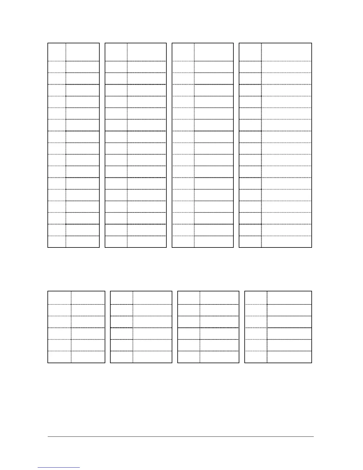
CPU128 – BPL128 Connector
Pin Signal Pin Signal Pin Signal Pin Signal
1 + 1 VDC 17 X13 33 + 12 VDC 49 X7
2 - 5 VDC 18 X12 34 - 5 VDC 50 X8
3 CS1 19 GNDCPU 35 A0 51 GNDCPU
4 CS2 20 X11 36 A1 52 X16
5 CONT1 21 X9 37 A2 53 X10
6 CS6 22 X17 38 CONT3 54 X14
7 CONT2 23 X15 39 DATA 55 X5
8 B 24 X0 40 RD 56 X22
9 DA1 25 X1 41 WR 57 X21
10 DA2 26 X2 42 CS3 58 X20
11 A 27 X18 43 DA0 59 X19
12 C 28 X3 44 D 60 X23
13 CS4 29 + 5 VDC 45 CS5 61 + 5 VDC
14 VAG 30 CS7 46 VAG 62 CS8
15 X4 31 GND 47 X6 63 GND
16 + 5 VDC 32 - 24 VDC 48 + 5 VDC 64 - 24 VDC
The data signals for the accessories are generated on CPU128, and then
transmitted to MS128 CPUKON via MS128 CPU-FC. The following table illustrates
the pin-out of the MS128 CPU-FC Flat Cable.
MS128 CPU-FC Cable
Pin Signal Pin Signal Pin Signal Pin Signal
1(red) XREL2 6 GNDCPU 11 OUT1 16 EMBT
2 XREL1 7 + 5 VDC 12 OUT2 17 RMF12
3 MUS1 8 DIAINP 13 - 24 VDC 18 GNDCPU
4 VAG 9 INP2 14 EMBR 19 BUSY
5 DIA 10 INP1 15 SERDATA 20 + 12 VDC
There is a LED on the front panel of CPU128. During normal operation it blinks
continuously. During a Reset or a Parameter Download it remains on. So, the state
of the system can be monitored by way of this LED.
 Loading...