Karel MS128 Installation & Maintenance Guide
Edition 3.2
72
III.9. STANDARD TELEPHONE SETS, EXTERNAL LINES,
POWER FAILURE TRANSFER STATIONS
• C
ABLING
:
For standard telephone sets and external lines :
The cabling of extension telephones and external lines are established
through the 2-pin connectors on KN1 and KN2 cards. Each connector
corresponds to an extension or line.
For connecting a standard telephone set to the system, the wires coming from
the corresponding connector on KN1 or KN2 card and passing through the
hole on the side covers of the system cabinet must be attached to the A / B
terminals of the telephone.
For connecting an external line to the system the wires of the cable coming
from the corresponding line connector on KN1 card and passing through the
hole on the side covers of the system cabinet must be attached to the
external line.
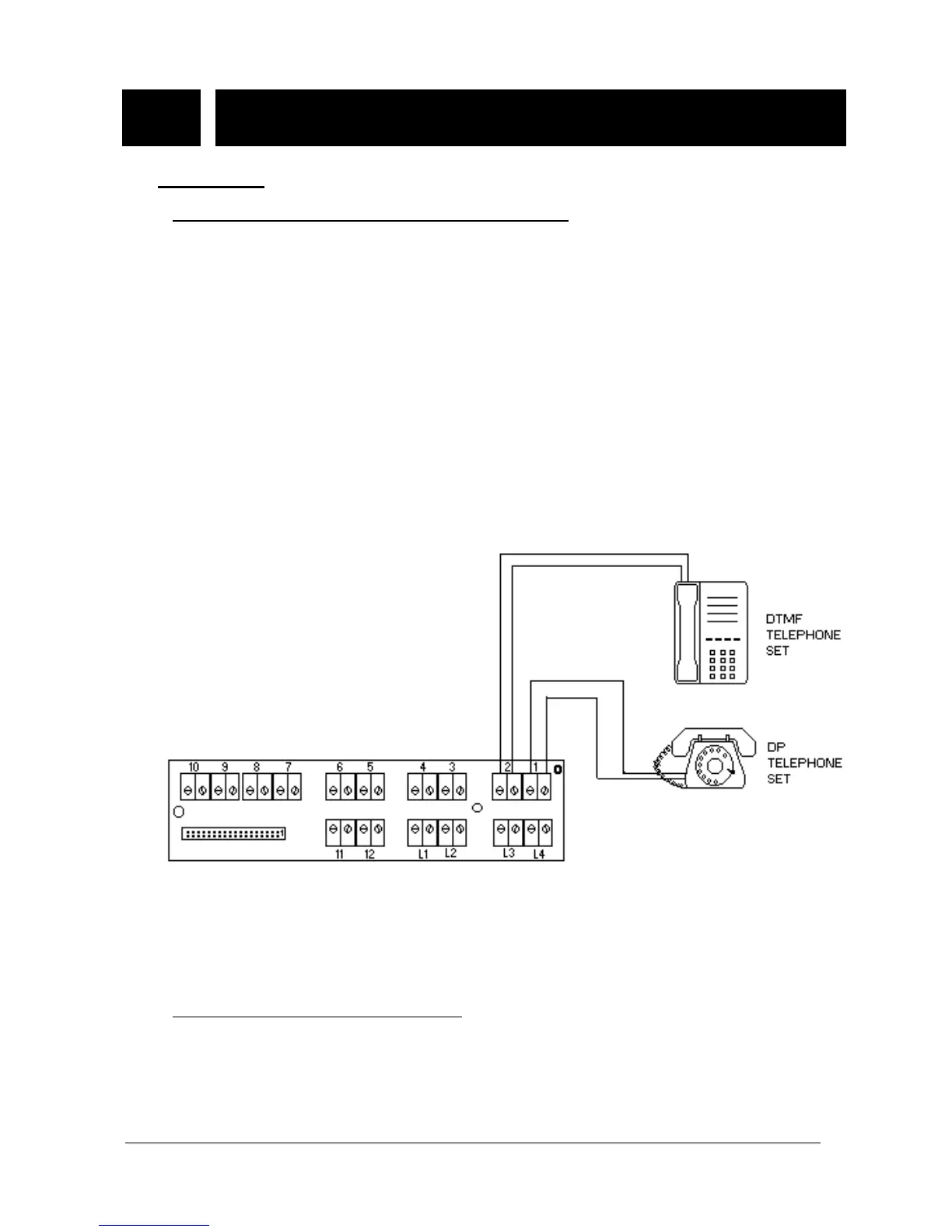
The following figure illustrate the cabling of standard telephones .
Figure B-29
Normally a standard telephone set can be connected as far as 2 km away
from the system by using ordinary copper wires. Depending on the quality of
the wires the distance changes proportionally.
For power failure transfer stations :
It is possible to connect any four lines directly to any four extensions in case of
power failure in the absence of battery backup. For this purpose, there are four
sets of triple connectors on the MS128 CPUKON card.
The left most connector in a set is used to make the connection of the line.
The middle one is used to make the connection of the extension circuitry and