Karel MS128 Installation & Maintenance Guide
Edition 3.2
67
Dip-switch 1 Dip-switch 2 Dip-switch 3 Dip-switch 4
First Adaptor
OFF OFF OFF OFF
Second Adaptor
OFF OFF ON OFF
Third Adaptor
OFF ON OFF OFF
III.7. AUTO-ATTENDANT & VOICE MAIL
• I
NSTALLATION
:
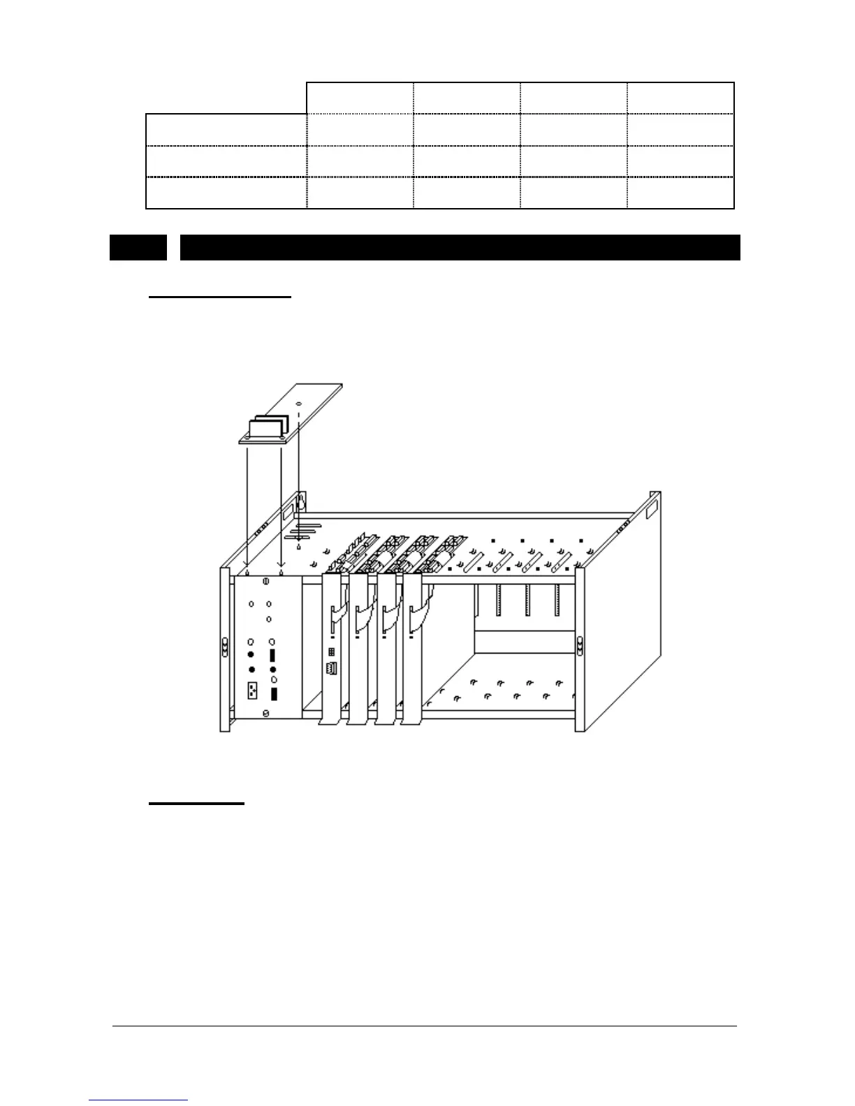
EVM128 card is placed to the empty space on top of the cabinet laying on
SPS128 and fixed to the space with three plastic holders. The figure below
illustrates this installation:
Figure B-24
• C
ABLING
:
The EVM128 card has a 10-pin connector on the component side of the card.
This has a correspondent on the MS128 CPUKON card. The 10-pin flat cable,
which comes with EVM128, is used to make the connections between these
connectors (see Figure B-25).
Additional EVM-FE (Auto Attendant Expansion) and EVM-DE (Voice Mail
Expansion) cards – if there exist any - must be installed on the EVM128 card
through 36-pin F1/F2 and 24-pin D1/D2/D3 connectors, respectively. The first
EVM-FE card must be installed to the Flash socket marked as F1, whereas the
second EVM-FE card must be installed to the socket marked as F2. The first
EVM-DE card must be installed on the DRAM socket marked as D1 and the