Karel MS128 Installation & Maintenance Guide
Edition 3.2
66
IMPORTANT
The first channel of the IA12 motherboard or EXP-IA12 card must be
connected to an odd numbered line (i.e. 01, 03, 05,….,19) and the second
channel must be connected to the succeeding even numbered line.
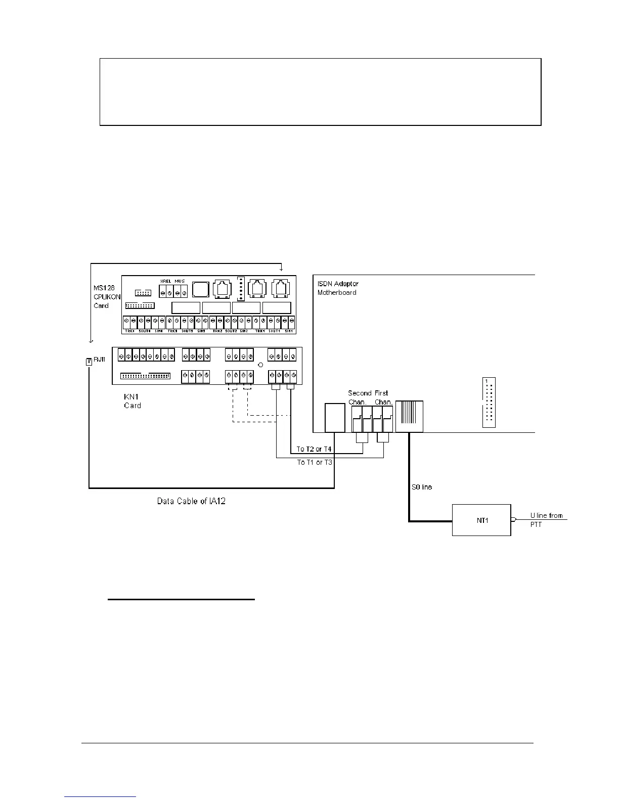
As illustrated in the figure below, while making the analog line connection as
explained above, the first channel on the IA12 motherboard or EXP-IA12 card
must be connected to line 01 or line 03 or so on. Then, if the first channel is
connected to line 01, the second channel must be connected to line 02 or if the
first channel is connected to line 03, the second channel must be connected to
line 04 or so on.
The following figure illustrates the wiring between MS128 system and IA12
motherboard .
Figure B-23
• D
IP
-
SWITCH SETTING
:
There exists four dip-switches on the IA12 motherboard, that can be accessed
upon opening the top cover. These dip-switches are used to distinguish the
IA12 ISDN Adaptors connected to the system. For the first adaptor all the dip-
switches must be OFF. For the second one the dip-switch “3” must ON and the
others must be OFF and for the third one (which can have only the IA12
motherboard) the dip-switch "2" must be ON and the others must be OFF. To
make it clear the following table is given: