Do you have a question about the KaVo FOCUS 215720 and is the answer not in the manual?
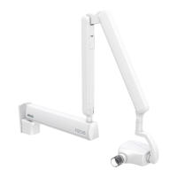
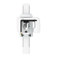
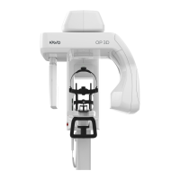
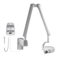
Overview of the microprocessor controlled intraoral X-ray unit with HF DC generator.
Specifies the unit's purpose for diagnostic X-ray radiographs of dental structures.
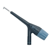
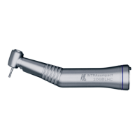
Identifies and lists the primary physical components of the FOCUS intraoral X-ray unit.
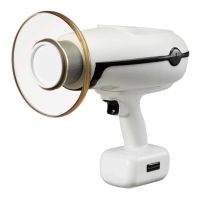
Details the different types of cones available for the X-ray unit, including dimensions.
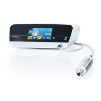
Explains the meaning of various symbols displayed on the remote control panel.
Outlines essential requirements for radiation protection, mounting, and electrical systems before installation.
Lists the necessary tools and hardware required for the installation process.
Provides a visual overview and sequential steps for the entire installation process.
Details the process of installing the mounting system, including wall plates and adapters.
Instructions for mounting the unit using a narrow wall mounting plate, including positioning and templates.
Guidance for installing the unit with a wide wall mounting plate on studs.
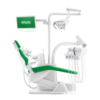
Steps for integrating the X-ray unit with a KaVo treatment unit using specific adapters.
Instructions for installing the OpenMount configuration, featuring a fixed shaft mounted to a horizontal arm.
Procedure for mounting and leveling the horizontal arm bracket to the wall.
Guidance on routing cables and fitting the scissors arm into its bearing on the horizontal arm.
Steps to adjust the friction brakes on the horizontal arm for proper movement and stability.
Detailed instructions for adjusting the friction brake located at the outer end of the horizontal arm.
Procedure for ensuring the horizontal arm is perfectly level using adjuster screws and a spirit level.
How to adjust the tension of the springs in the scissors arm for optimal balance and movement.
Instructions for installing the remote control unit, including wall and treatment unit mounting, and terminal strip connection.
Instructions for securely mounting the remote control unit to a wall using drilling templates and screws.
Steps to remove and prepare the control panel for integration with a dental treatment unit.
Alternative method for connecting the remote control panel using a terminal strip instead of an RJ-45 connector.
Configuration of DIP switches on the remote control and connection box for various operational modes.
Illustrates DIP switch settings for a configuration with one remote and specific switch inputs.
Shows DIP switch settings for a setup with one remote and two exposure switches in series.
Demonstrates DIP switch settings for two remotes using a selector switch and individual exposure switches.
Configuration example for using the remote control and an external exposure button in series.
Guides on connecting the unit's power supply, differentiating between permanent and non-permanent installations.
Distinguishes between permanent and non-permanent electrical connections, detailing fuse usage for each.
Instructions on how to change a unit wired with a plug to a permanent installation, including mains switch requirement.
Guidance on reverting a permanent installation back to a non-permanent (plug-in) configuration.
Specific instructions for a permanent electrical installation of the unit using 115 VAC.
Procedure for safely removing and replacing fuses in the X-ray unit, including fuse types and ratings.
Instructions for attaching the protective covers to the assembled X-ray unit.
Procedure for calibrating the unit by performing specific exposure sequences before initial operation.
Essential checks after installation covering movement, safety, and unit functions.
Technical drawings and dimensions for the wide wall mounting plate.
Technical specifications and dimensions for the narrow wall mounting plate.
Dimensional drawings of the mounting frame for the remote control unit.
Overall dimensions and reach specifications for wall-mounted installations.
Technical drawings and dimensional data specific to the OpenMount configuration installation.
| Brand | KaVo |
|---|---|
| Model | FOCUS 215720 |
| Category | Medical Equipment |
| Language | English |