4
Figure 3- 2
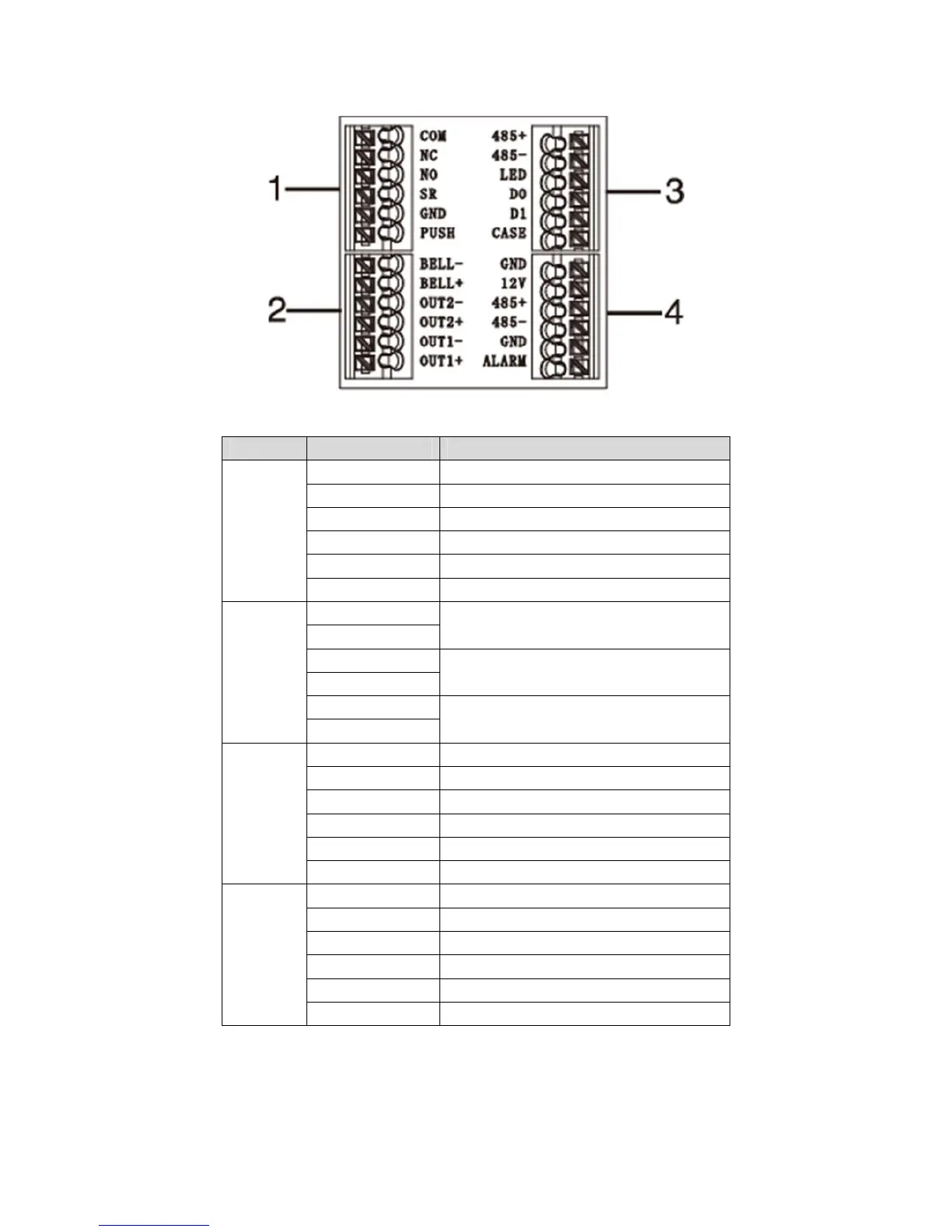
No. Port Note
1 COM Door lock COM end
NC Door lock NC end
NO Door lock NO end
SR Door sensor detection
GND Connect to GND
PUSH Press unlock button
2 BELL- Door bell output
BELL+
OUT2-
Alarm output 2 ( 5V level switch ),
connect to voltage not over 12V
OUT2+
OUT1-
Alarm output 1(5V level switch), connec
to voltage not over 12V
OUT1+
3 485+ RS485+, 485 card reader
485- RS485-, 485 card reader
LED LED_OUT, Weigand card reader
D0 D0, Weigand card reader
D1 D1, Weigand card reader
CASE Card reader protection alarm
4 GND Connect to GND
12V 12V power input
485+ RS485+
485- RS485-
GND Connect to GND
ALARM Alarm input