© Copyright 2017 KE2 Therm Solutions, Inc., Washington, Missouri 63090
Q.3.29 May 2017 supersedes Q.1.29 November 2014 and all prior publications.
KE2 LowTemp
Quick Start Guide
Q.3.29 (Q.1.29) May 2017
Page 20
KE2 Therm Solutions
12 Chamber Drive . Washington, MO 63090
1-888-337-3358 . www.ke2therm.com
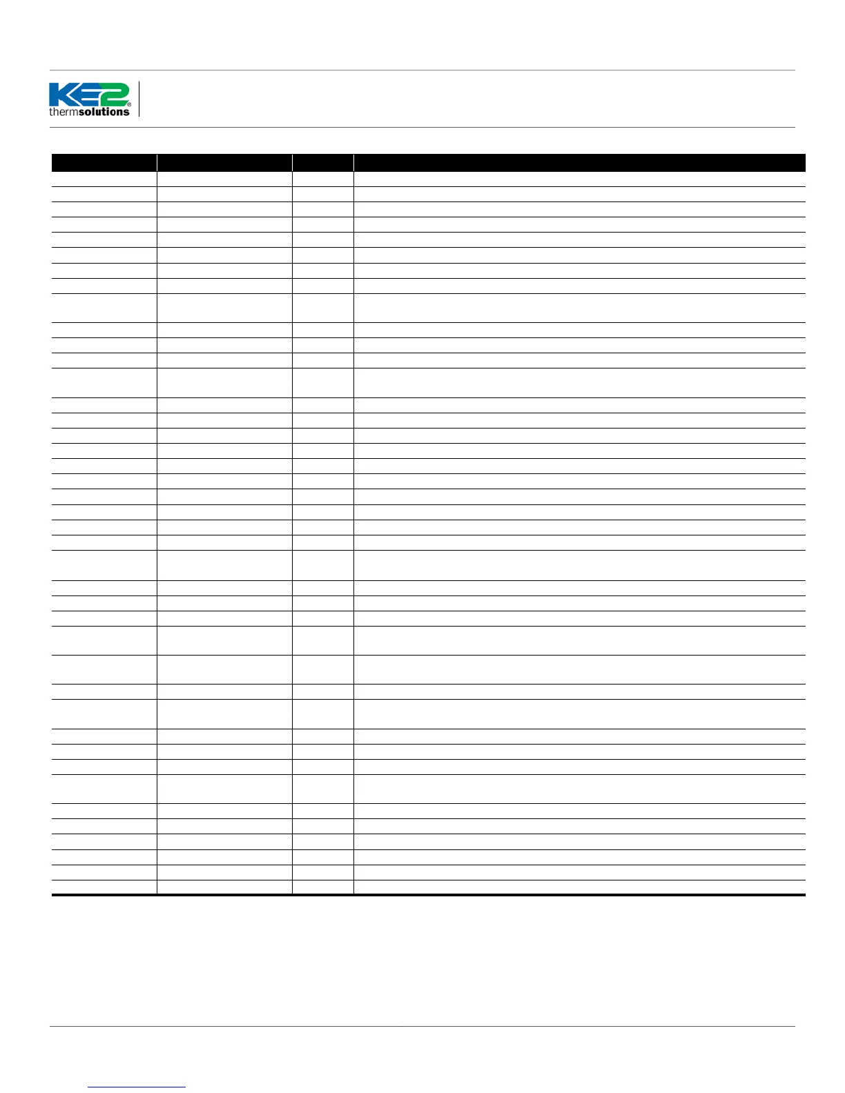
Abbreviations - Alphabetical Listing (continued)
Abbreviation Name Type Description
ELEC ELEC Electric Setpoint Defrost option
FAH FAH Fahrenheit Setpoint Default for all temperatures displayed
FdSP FdSP Fan delay temp Setpoint Setpoint Coil temp must reach this setpoint to turn fans back on after defrost
FndF FndF Fan State During Defrost Setpoint Fans on or o during defrost
FndL FndL Fan Delay System State Displays when system is in fan delay mode
Fndt Fndt Max fan delay time Setpoint Maximum time system can stay in fan delay (FndL) mode
FnrL FnrL Fan Relay Variable Status of whether fan relay is energized or de-energized
FrEF FrEF Fan mode during refrigeration Setpoint Fan on or cycling during refrigeration mode
HtA HtA High Temperature Alarm Alarm
Average temperature is above the Temperature Setpoint (tS) + Temperature Dierential Setpoint diF + High Alarm
Oset (HAO) for the amount of time in the Temperature Alarm Delay (tAd)
HAO HAO High Alarm Oset Setpoint Number of degrees above the Temperature Setpoint (tS) for a High Temp Alarm (HtA) condition.
inid inid Inititate Defrost Variable Choice for input type for 1st or 2nd Auxiliary input (AU1 or AU2) - digital input that will initiate defrost
LAO LAO Low Alarm Oset Setpoint Number of degrees below the Temperature Setpoint (tS) for a Low Temp Alarm (LtA) condition.
LtA LtA Low Temperature Alarm Alarm
Average temperature is below the Temperature Setpoint (tS) - Low Alarm Oset (LAO) for the amount of time in the
Temperature Alarm Delay (tAd)
NOAL NOAL No Alarm Alarm System is clear of alarms
OFF OFF System O System State The system is currently not running
OnCP OnCP On with compressor Setpoint Fans are on when compressor is running
OPEn OPEn Open Setpoint Digital input is active/inactive when open
Pdt Pdt Defrost pump down time Setpoint Amount of time to pump down the system before defrost
PErn PErn Permanent Setpoint Fans on permanently
PF PF Power Failure alarm Alarm Alarm indicates that there was an interruption in the power supply to the controller
rEFr rEFr Refrigerate Mode System State System mode displayed when controller is in cooling mode
rt1 rt1 Room Temperature 1 Variable Room temperature displayed if AU1 (1st Auxiliary input) is set to rtP (Room Temp)
rt2 rt2 Room Temperature 2 Variable Room temperature displayed if AU2 (2nd Auxiliary input) is set to rtP (Room Temp)
rtP rtP Room Temp Variable
Choice for input type for 1st or 2nd Auxiliary input (AU1 or AU2) - input is used as an additional room temperature
averaged in with the other room temperature inputs
SHrt SHrt Short Setpoint Digital input is active/inactive when short
StA1 StA1 State of 1st Auxiliary Input Setpoint Digital input active state for 1st Auxiliary input (AU1) - set whether it is open or short
StA2 StA2 State of 2nd Auxiliary Input Setpoint Digital input active state for 2nd Auxiliary input (AU2) - set whether it is open or short
SYOF SYOF System O Variable
Choice for input type for 1st or 2nd Auxiliary input (AU1 or AU2)- digital input that puts the controller into System
O Mode
SYOn SYOn System On Variable
Choice for input type for 1st or 2nd Auxiliary input (AU1 or AU2)- digital input that puts the controller into System
On Mode
SYSt SYSt System State Variable Displays mode of system operation
t2nd t2nd 2nd Room Temp Setpoint Setpoint
Choice for input type for 1st or 2nd Auxiliary input (AU1 or AU2) - input is used to switch between the main Room
Temp Setpoint and the 2nd Room Temp Setpoint
t2Of t2Of 2nd Air O Variable Use main air temperature setpoint
t2On t2On 2nd Air On Variable Use second air temperature
tAd tAd Temp Alarm Delay Setpoint Amount of time to delay a high temp or low temp alarm
tErd tErd Terminate Defrost Variable In Variables menu, display when 1st or 2nd Auxiliary input (AU1 or AU2) set to trdF (terminate defrost) and is active
ti24 ti24 Title 24 Setpoint Congure the controller to be Title 24 for runtime compliant during refrigeration system’s o cycle
tOd tOd Time of day Setpoint Time is displayed based on 24 hour clock
trdF trdF Terminate Defrost Setpoint Choice for input type for1st or 2nd Auxiliary input (AU1 or AU2) - digital input that will terminate defrost
tS tS Temperature Setpoint Setpoint Room temperature to be maintained
tS2 tS2 Temperature Setpoint 2 Setpoint Alternate room temperature setpoint
Unt Unt Temp units Setpoint Fahrenheit (FAH) or Celsius (CEL)
 Loading...