© Copyright 2017 KE2 Therm Solutions, Inc., Washington, Missouri 63090 © Copyright 2017 KE2 Therm Solutions, Inc., Washington, Missouri 63090
KE2 LowTemp
Quick Start Guide
KE2 LowTemp
Quick Start Guide
Q.3.29 (Q.1.29) May 2017
Page 8
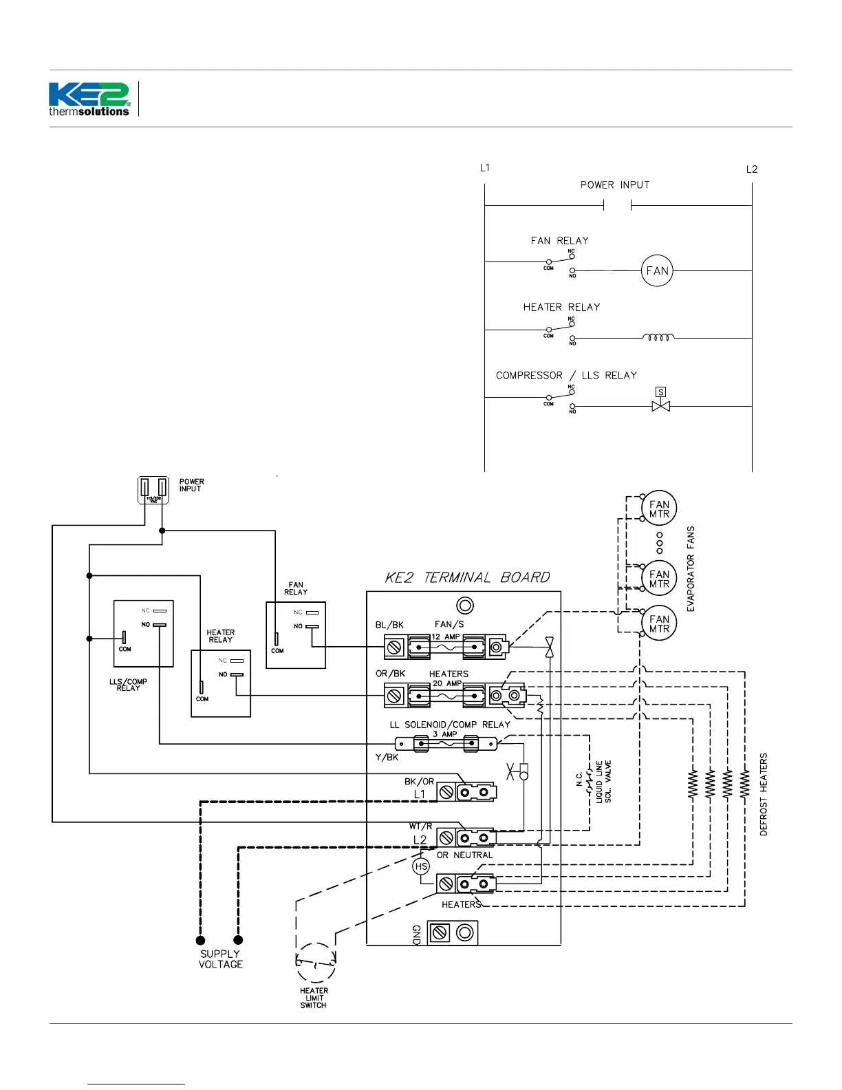
Wiring Schematic - Ladder Diagram:
Figure 2 - Wiring Schematic - Using KE2 Terminal Board
When using existing terminal board in the evaporator
When using existing terminal board in the evaporator, re-
fer to the ladder diagram, Figure 1. Note that the relays on
the controller constitute switch legs only, no power is di-
rectly supplied out of the relay terminals. Assure that the
controller has a constant source of power and the voltage
is properly selected as shown in step 6. The relays may
switch any single phase voltage up to 240 vac.
Wiring schematic using the optional KE2 Therm termi-
nal board, pn 20996, and a KE2Therm wiring harness.
Using the KE2 Therm terminal board and wiring harness
reduces the potential for wiring errors. See Figure 2 be-
low, and step by step instructions 14 - 19 on the following
pages.
Figure 1 -
Ladder Diagram

 Loading...