© Copyright 2017 KE2 Therm Solutions, Inc., Washington, Missouri 63090 © Copyright 2017 KE2 Therm Solutions, Inc., Washington, Missouri 63090
KE2 LowTemp
Quick Start Guide
KE2 LowTemp
Quick Start Guide
Q.3.29 (Q.1.29) May 2017
Page 6
8
8
9
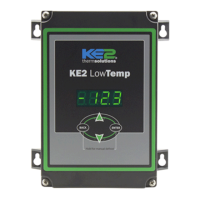
Defrost (Heater) Relay
Strip the end of the 2 wires used for the defrost control.
Locate 2 additional 90° female spade connectors in the accessories
kit.
Crimp on the female connectors.
Plug the connectors to the COM and NO positions of the Defrost
Relay.
Conrm combined heater load is not over 30 amps.
9
10
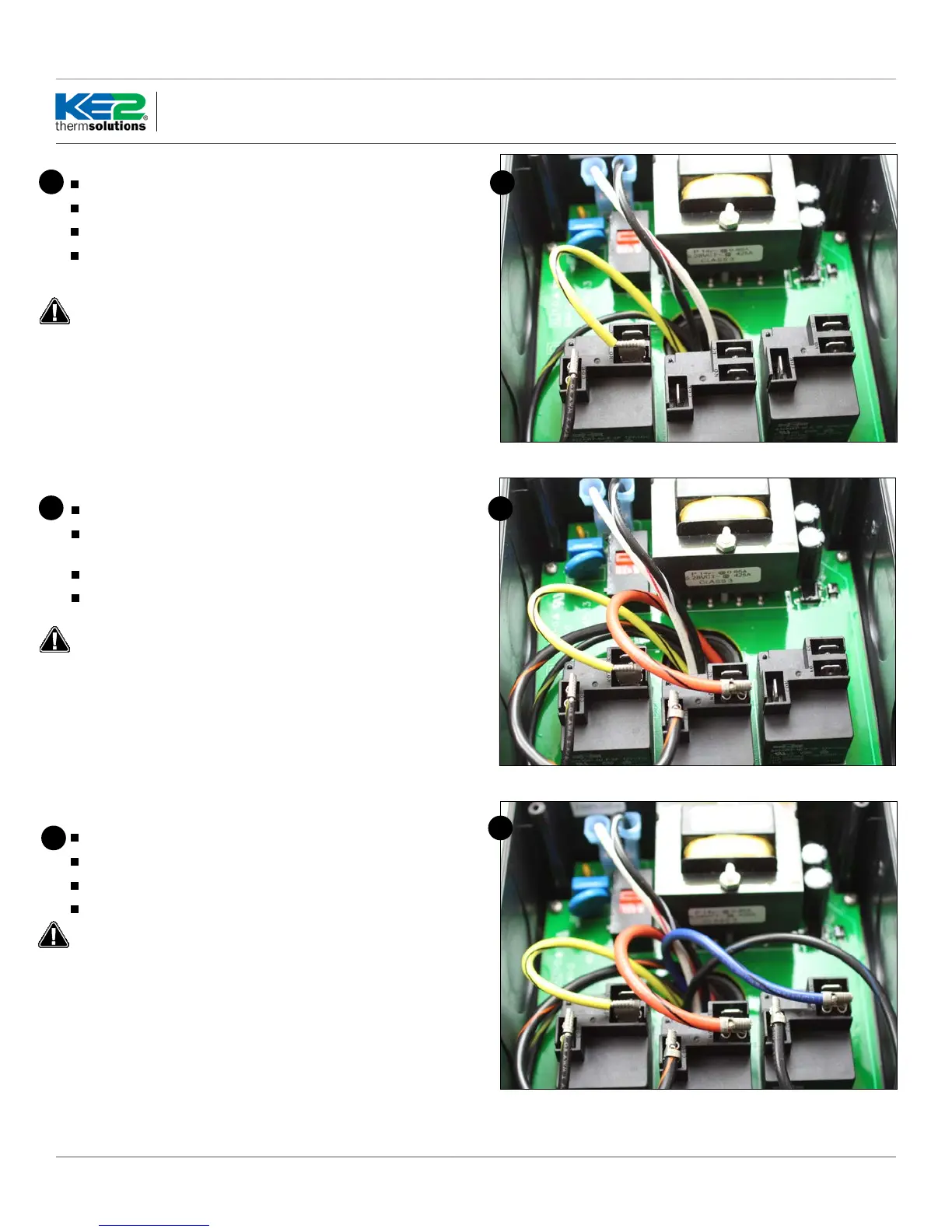
Liquid Line Solenoid /Compressor Relay
Strip the end of the 2 wires used for the liquid line solenoid.
Locate 2 90° female spade connectors in the accessories kit.
Crimp on the female connectors.
Plug the connectors to the COM and NO positions of the Liquid
Line Solenoid /Compressor Relay
Conrm compressor load is not over 30 FLA.
Fan Relay
Strip the end of the 2 wires used for fan control.
Locate 2 90° female spade connectors in the accessories kit.
Crimp on the female spade connectors.
Plug the connectors to the COM and NO positions of the Fan Relay.
Conrm combined fan motor load is not over 30 FLA.
10
 Loading...