Do you have a question about the KE2 Therm Solutions KE2 Temp + Defrost and is the answer not in the manual?
| Model | KE2 Temp + Defrost |
|---|---|
| Operating Temperature | -40°F to 140°F (-40°C to 60°C) |
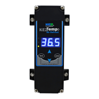
| Display Type | LCD |
| Defrost Initiation Method | Time or Temperature |
| Communication Protocol | Modbus RTU |
| Communication | RS-485 |
| Enclosure Rating | NEMA 1 |
| Input Power | 24 VAC/DC ± 10% |
| Power Supply | 24 VAC/VDC |
| Humidity | 0 to 95% RH (non-condensing) |
| Defrost Type | Electric, Hot Gas |
| Defrost Termination Temperature | Adjustable |
| Defrost Duration | Adjustable |
| Temperature Differential | Adjustable |
| Analog Inputs | 2 Temperature Sensors |
| Digital Inputs | 1 Digital Input |
Lists controller, sensor, screws, cord grip, ziptie, and programming sticker.
Lists conduit, connectors, wires, insulation, and sealing materials.
Specifies mounting location under a counter.
Details mounting for walk-in and side-by-side applications.
Highlights remote access via KE2 LDA and Modbus.
Explains the indicator for post-defrost cycle status.
Instructions for removing the controller display and high voltage cover.
Connecting power supply terminals and setting voltage selector.
Connecting L1 and L2 to the correct terminal positions.
Wiring the liquid line solenoid or compressor relay.
Connecting temperature sensor and Modbus communication.
Details network access via KE2 LDA and internet portal.
Overview of webpage interface for monitoring and adjustments.
Explains button operations for accessing setpoints and making changes.
Lists and defines available setpoints like tS, diF, CSH, dPd.
Describes the meaning of the controller's indicator lights.
Defines minimum, default, and maximum values for basic setpoints.
Lists advanced setpoints visible when custom defrost is selected.
Step-by-step guide for configuring custom defrost times and parameters.
Explains the military time format for setting defrost times.
Provides physical dimensions of the controller unit in inches.
Illustrates electrical connections for power and components.