Do you have a question about the KEB COMBIVERT Series and is the answer not in the manual?
Details the contents of the manual, including safety and installation.
Covers general safety, qualified personnel, and proper use of the device.
Essential guidelines for safe transport, storage, and installation procedures.
Specifics on installation requirements and electrical connection steps.
Key operating procedures, including automatic restart and safety.
Basic EMC concepts and initial installation recommendations.
Steps for installing the unit within an EMC compliant cabinet.
Detailed explanations on EMC phenomena and proper shielding techniques.
Guidelines for connecting control lines to maintain EMC performance.
Details on CE marking and compliance with EU directives.
Information on obtaining manufacturer declarations for product compliance.
This document serves as a comprehensive guide for the installation, operation, and maintenance of KEB COMBIVERT frequency inverters and servo drives. It emphasizes safety, proper application, and adherence to EMC (Electromagnetic Compatibility) standards to ensure reliable and trouble-free performance.
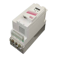
KEB COMBIVERT frequency inverters and servo drives are sophisticated drive components designed for the stepless speed regulation and control of three-phase asynchronous and permanent magnet motors. They are intended for integration into electrical systems or machines, providing precise control over motor speed and torque. These devices are crucial for applications requiring variable speed, high accuracy, and dynamic response in industrial and commercial environments. The inverters and servo drives convert incoming AC power into a variable frequency and voltage output, which then controls the motor's speed. They are equipped with advanced control algorithms to optimize motor performance and energy efficiency. The system can be configured to handle various operational modes, including those requiring braking resistance, and offers protective functions against overloads and short-circuits.
The COMBIVERT units are designed for stationary installation and require proper earthing. They are suitable for vertical mounting, allowing for side-by-side placement with a minimum clearance of 50mm from other elements to ensure adequate cooling. The units are built to operate in specific environmental conditions, as outlined in EN 50178, and must be protected from mist, water, dust, and aggressive gases or liquids.
For optimal performance and EMC compliance, the use of original KEB cables for motor and transmitter connections is recommended. The installation process involves careful separation of power cables, control lines, and data lines to prevent coupled-in noise, with a minimum separation of 15 cm between different cable types. Shielded and twisted control lines are essential, with shields connected to PE at the inverter only.
The devices are designed for fixed connections, especially when using EMI filters, due to potential discharge currents exceeding 3.5 mA. This necessitates a protective conductor with a cross-section of at least 10mm² (copper) or a second protective conductor in compliance with EN 50178, ensuring a point-to-point ground connection to mains earth.
The COMBIVERT units are conditionally short-circuit proof, meaning that after internal protection devices reset, the function is guaranteed. However, frequent earth-leakage faults or short-circuits at the output, or short-circuits during regenerative operation, can lead to unit defects.
For applications requiring cyclic activation and deactivation, an off-time of at least 5 minutes should be maintained. Shorter cycle times may be possible but require consultation with KEB.
Before any installation, connection, or maintenance work, the system must be switched off and secured. A critical safety feature is the capacitor discharge time: after switching off, the intermediate circuit capacitors remain charged with high voltage for a short period. It is imperative to wait at least 5 minutes after power-off before working on the unit to allow for complete discharge.
The control terminal strip and transmitter inputs are securely isolated in accordance with EN 50178, but the installer must ensure that all existing or newly wired circuits meet EN requirements.
Regular checks of terminals and screw connections for tightness are necessary before putting the unit into operation. All covers must be properly reinstalled.
The manual highlights the importance of monitoring the braking resistance temperature switch to prevent overload and fire hazards. This sensor should be connected as described in Part 2 of the instructions. However, this measure alone is insufficient if the braking transistor is defective; in such cases, disconnecting the mains voltage is the only way to avert extreme overload.
For systems requiring personnel protection, frequency inverters must be protected according to EN 50178, using RCD type A or B for 1-phase inverters, and RCMA's or RCD's type B for 3-phase inverters. The tripping current should be 300mA or more to avoid premature triggering by discharge currents.
The service life of the frequency converter/servo drive, particularly the electrolytic capacitors in the intermediate circuit, is influenced by the current load. The use of mains chokes can significantly extend the service life of these capacitors, especially when connected to "hard" power systems or under continuous drive load. KEB recommends mains chokes with a terminal voltage (Uk) of 4% for continuous duty (S1) drives with a medium duty of >60%. When a mains choke is used, it should typically be mounted on the mains side of the interference suppression filter.
The manual also emphasizes the importance of a manufacturer's declaration in accordance with 89/392/EEC, which can be provided by KEB if needed, ensuring compliance with relevant directives.
| Category | DC Drives |
|---|---|
| Enclosure Rating | IP20 |
| Series | COMBIVERT |
| Protection Features | Overcurrent, overvoltage, undervoltage, short circuit, overtemperature |
| Communication Interfaces | CANopen |
| Ambient Temperature | 0 - 45°C (32 - 113°F) |
| Cooling Method | Fan Cooled |