F96VTN and G96VTN: Installation, Start-up, Operating and Service and Maintenance Instructions
Manufacturer reserves the right to change, at any time, specifications and designs without notice and without obligations.
55
Adjust Manifold Pressure
1. Adjust manifold pressure to obtain low fire input rate. See Fig. 63.
A170117
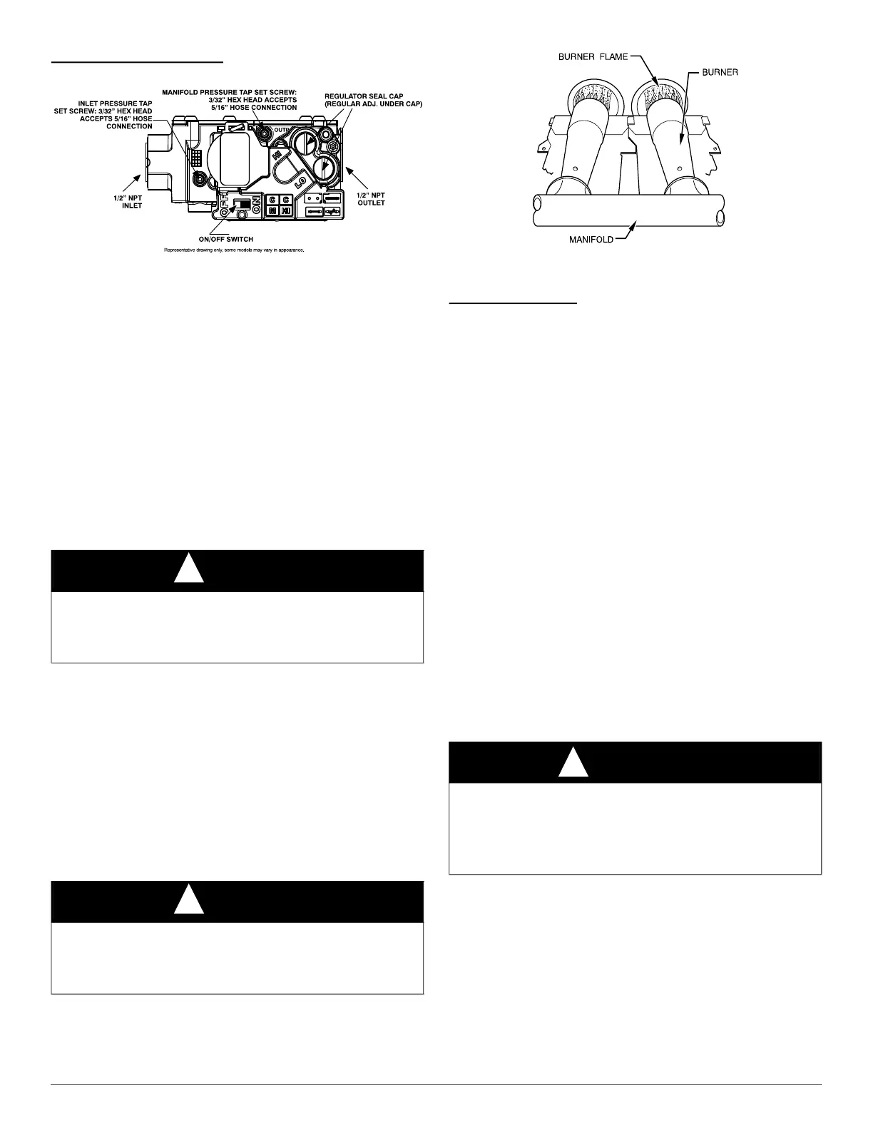
Fig. 63 – Gas Valve with Tower Pressure Ports
a. Turn gas valve ON/OFF switch to OFF.
b. Loosen set screw on manifold tower pressure tap no more than
one full turn with a 3/32-in. hex wrench, or remove the 1/8 inch
NPT plug from the manifold pressure tap on the gas valve.
c. Connect a water column manometer or similar device to
manifold pressure tap.
d. Turn gas valve ON/OFF switch to ON.
e. Move setup SW1-2 on furnace control to ON position to lock
furnace in low-heat operation. See Fig. 59 and Fig. 38.
f. Manually close blower door switch.
g. Jumper R and W/W1 thermostat connections on control to start
furnace. See Fig. 38.
h. Remove regulator adjustment cap from low heat gas valve
pressure regulator and turn low-heat adjusting screw (3/16 or
smaller flat-tipped screwdriver) counterclockwise (out) to
decrease input rate or clockwise (in) to increase input rate. See
Fig. 63.
i. Install low-heat regulator adjustment cap.
j. Move setup switch SW1-2 to OFF position after completing
low-heat adjustment.
k. Leave manometer or similar device connected and proceed to
Step 2.
2. Adjust manifold pressure to obtain high fire input rate See Fig. 63.
a. Jumper R to W/W1 and W2 thermostat connections on furnace
control. This keeps furnace locked in high-heat operation.
b. Remove regulator adjustment cap from high-heat gas valve
pressure regulator and turn high heat adjusting screw (3/16-in. or
smaller flat-tipped screwdriver) counterclockwise (out) to
decrease input rate or clockwise (in) to increase input rate. See
Fig. 63.
c. When correct input is obtained, replace caps that conceal gas
valve regulator adjustment screws. Main burner flame should be
clear blue, almost transparent See Fig. 64.
A89020
Fig. 64 – Burner Flame
d. Remove jumpers R to W/W1 and R to W2.
Clocking the Meter
3. Verify natural gas input rate by clocking meter.
NOTE: Contact your HVAC distributor or gas supplier for metric gas
meter tables, if required.
a. Turn off all other gas appliances and pilots served by the meter.
b. Move setup switch SW1-2 to ON position. This keeps furnace
locked in low-heat operation when only W/W1 is energized.
c. Jumper R to W/W1.
d. Run furnace for 3 minutes in low-heat operation.
e. Measure time (in sec) for gas meter to complete one revolution
and note reading. The 2 or 5 cubic feet dial provides a more
accurate measurement of gas flow.
f. Refer to Table 21 for cubic ft. of gas per hr.
g. Multiply gas rate cu ft./hr by heating value (BTUh/cu ft.) to
obtain input rate.
h. If clocked rate does not match required input from Step 1,
increase manifold pressure to increase input or decrease manifold
pressure to decrease input. Repeat steps b through e of Step 1
until correct low-heat input is achieved. Re-install low heat
regulator seal cap on gas valve.
i. Jumper R to W/W1, and W2. This keeps furnace locked in
high-heat operation when both W/W1 and W2 are energized.
j. Repeat items d through g for high-heat operation, repeating Step
2 and adjusting the high-heat regulator screw as required.
4. Restore furnace to normal operating condition.
a. Turn gas valve ON/OFF switch to OFF.
b. Remove water column manometer or similar device from
manifold pressure tap.
c. Tighten set screw on manifold pressure tap with 3/32-in. hex
wrench, or if ⅛-in. NPT plug was removed, apply pipe dope
sparingly to end of plug and re-install in the gas valve.
d. Turn gas valve ON/OFF switch to ON.
e. Move setup SW1-2 on furnace control to position required for
attached thermostat (OFF for single-stage thermostats, ON for
two-stage thermostats).
f. Check for gas leaks and verify furnace operation.
Adjust Temperature Rise
NOTE: Blower door must be installed when taking temperature rise
reading. Leaving blower door off will result in incorrect temperature
NOTICE
!
DO NOT set low-heat manifold pressure less than 1.3-in. w.c. (324 Pa)
or more than 1.7 in. w.c. (423 Pa) for natural gas. If required manifold
pressure is outside this range, change main burner orifices to obtain
manifold pressure in this range.
NOTICE
!
DO NOT set high-heat manifold pressure less than 3.2-in. w.c. (797 Pa)
or more than 3.8 in. w.c. (947 Pa) for natural gas. If required manifold
pressure is outside this range, change main burner orifices to obtain
manifold pressure in this range.
WARNING
!
FIRE HAZARD
Failure to follow this warning could result in personal injury, death,
and/or property damage.
Manifold pressure tap set screw must be tightened or 1/8-in. NPT pipe
plug must be installed to prevent gas leaks.