Performance Ve rification
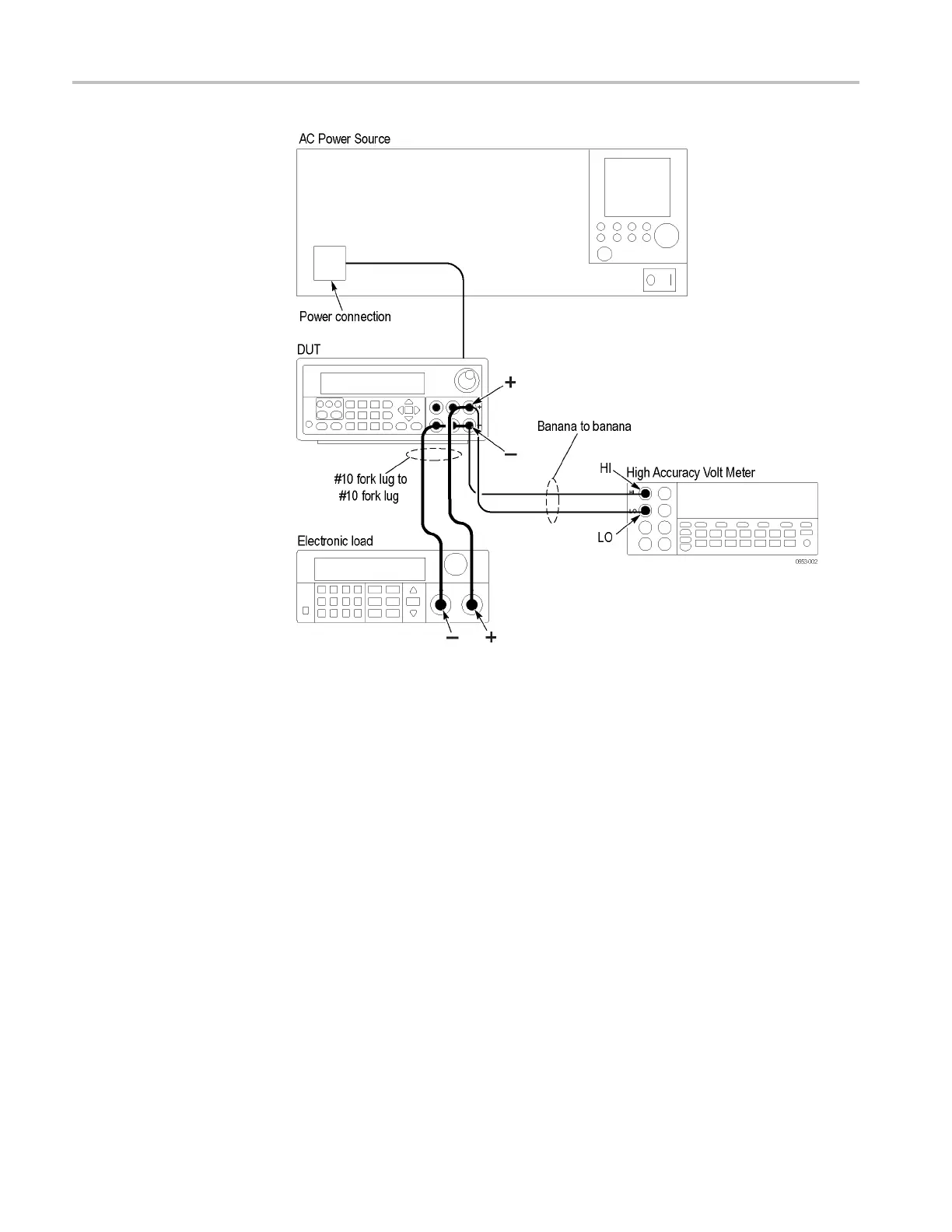
Figure 5: Voltage accuracy, regulation, and protection test setup. The channel
1 test setup is shown.
2. Set the voltmeter as follows:
a. Set to measure DC volts.
b. Set to auto range.
c. Verify that the Math mx+b function is disabled (shift DCV), assuring that
volts are being read.
3. Set the electronic load as follows:
a. Set to Constant Current.
b. Set to draw a constant current at the test current specified for the channel
under test (CUT) in the table for checking DC Voltage Accuracy without
Remote Sense. (See Table 16 on p age 17.)
4. Set the CUT to the full scale (FS) output current.
5. Set the CUT to 0% of the FS output voltage (0 V).
6. Turn the DUT output on.
32 Series 2200 Multichannel Programmable DC Power Supplies Technical Reference

 Loading...


