Performance Ve rification
Check DC Voltage Line
Regulation
This check proc
edure uses the same test setup as the previous procedure. (See
Figure 5.)
For each channel sequentially.
1. Change the AC
Power Source output to the minimum voltage specified in the
following table.
NOTE. Ensure the warm-up criteria has been met as described in the Performance
Verification Conditions.
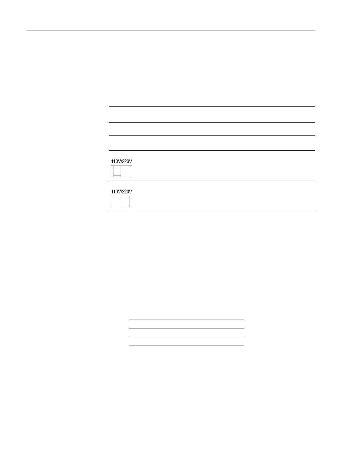
DUT voltage selector
switch AC Power Source voltage Japan configured units
110 99 V 90
220 198 V 180
2. Set the voltmeter as follows:
a. Set to measure DC volts.
b. Set t
o auto range.
c. Verify that the Math mx+b function is disabled (shift DCV), assuring that
volt
s are being read.
3. Set the electronic load as follows:
a. Set to Constant Current.
b. Set to draw the specified test current.
Instrument Test current
Channel 1
0.5 A
Channel 2
0.5 A
Channel 3
2.5 A
4. Set the channel under test (CUT) to 100% of the full scale (FS) output current.
5. Set the CUT to 100% of the FS output voltage.
6. Turn the DUT output on.
34 Series 2200 Multichannel Programmable DC Power Supplies Technical Reference

 Loading...


