Section Figure Title Page
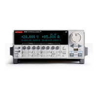
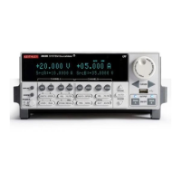
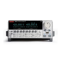
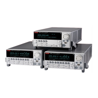
1 Figure 1-1 Models 2601, 2611, 2602, 2612, 2635, and 2636 front panels...... 1-3
1 Figure 1-2 Model 2601/2602/2611/2612 rear panels ...................................... 1-6
1 Figure 1-3 Model 2635 and 2636 rear panels ................................................. 1-8
1 Figure 1-4 Model 2602/2612 Low-Noise Chassis Ground Banana Jack and
Chassis Screw...............................................................................1-14
1 Figure 1-5 Interlock circuit............................................................................. 1-15
1 Figure 1-6 Display modes ............................................................................. 1-15
1 Figure 1-7 Buffer display format.................................................................... 1-18
2 Figure 2-1 GPIB cable..................................................................................... 2-2
2 Figure 2-2 RS-232 cable ................................................................................. 2-2
2 Figure 2-3 Test Script Builder initial startup screen......................................... 2-5
2 Figure 2-4 Instrument console control icons ................................................... 2-6
2 Figure 2-5 Select Instrument Resource dialog box ......................................... 2-7
2 Figure 2-6 Source-measure command sequence in console window
(2601/2602 version shown)............................................................ 2-9
2 Figure 2-7 LabVIEW source-measure example block diagram..................... 2-11
2 Figure 2-8 Visual Basic example user interface............................................ 2-12
2 Figure 2-9 Example program test results ...................................................... 2-14
3 Figure 3-1 Pulse-measure cycle for the PulseVMeasureI function............... 3-3
3 Figure 3-2 Importing a factory script project from the Series 2600 ................. 3-6
3 Figure 3-3 KIGeneral project imported into the Test Script Builder ................. 3-7
3 Figure 3-4 Run configuration example - Main tab shown................................ 3-9
3 Figure 3-5 Run configuration example - Script Attributes tab shown ............ 3-10
3 Figure 3-6 LabVIEW source step example ................................................... 3-12
3 Figure 3-7 GUI after loading the non-function script (GPIB) ......................... 3-15
3 Figure 3-8 GUI after running the non-function script (GPIB)......................... 3-16
3 Figure 3-9 GUI after loading and running the function script (GPIB) ............ 3-18
3 Figure 3-10 GUI after calling the function (GPIB) ........................................... 3-19
4 Figure 4-1 TSP-Link connections.................................................................... 4-2
B Figure B-1 Digital I/O port terminals ................................................................ B-3
B Figure B-2 Triggering a scanner...................................................................... B-3
B Figure B-3 Stacking channels for higher voltage ............................................. B-7
B Figure B-4 Connecting channels in parallel for higher current ........................ B-8
B Figure B-5 Model 2601/2602/2611/2612 contact check connections .............. B-9
B Figure B-7 Model 2635/2636 low-current connections.................................. B-10
List of Figures
 Loading...
