Series 3700 Screw Terminal Installation Instructions
PA-955 Rev. E / April 2010 9
2. Wire the screw terminal assembly circuit board:
CAUTION It is not necessary to remove a circuit board from its enclosure to wire the screw
terminal assembly. Avoid handling circuit board surfaces and terminal blocks,
because contaminants from hands may degrade the screw terminal assembly's
performance.
a. For screw terminal assemblies that include insertable overlays, select the correct overlay for the
configuration you are using and press it into place inside the screw terminal assembly.
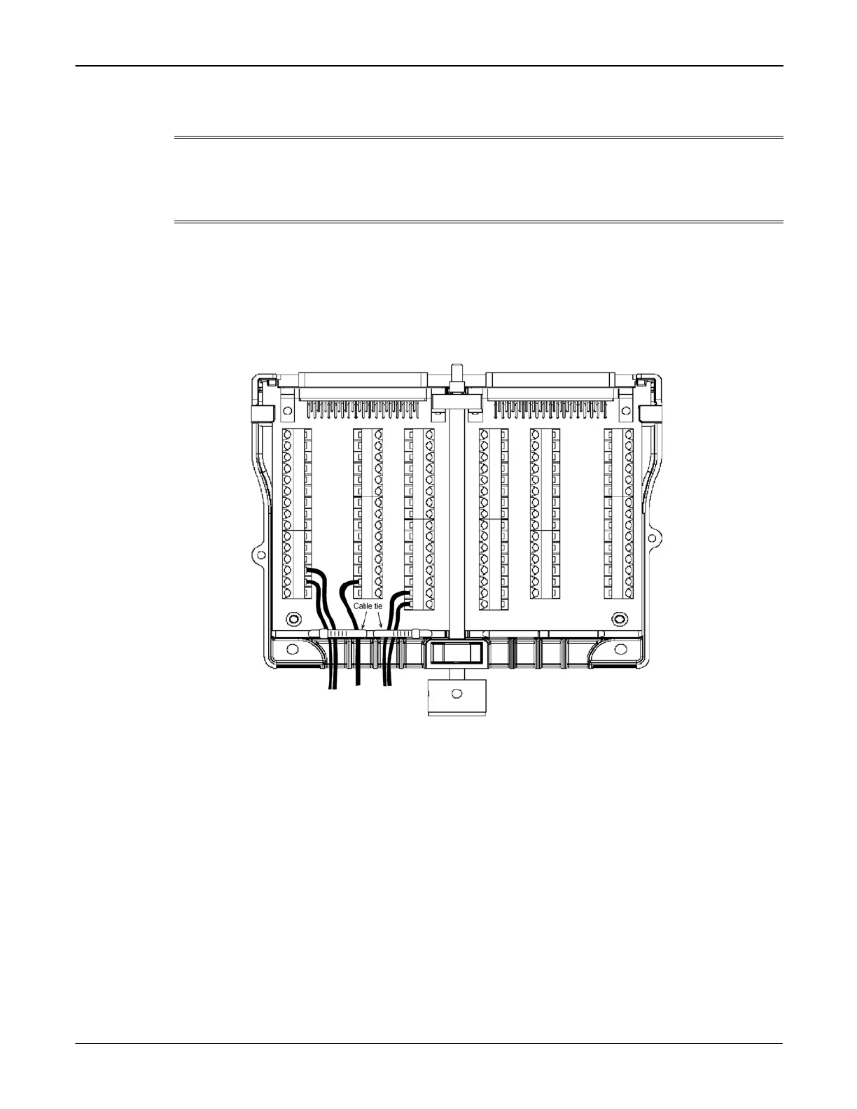
b. As shown in Figure 10, ro
ute your wiring through the slots in the rear of the screw terminal assembly
and connect it to the proper wiring terminals (refer to the documentation supplied with your switch card
for proper connection information).
Figure 10: Routing and securing cables with ties
c. When all wires have been connected, use small cable ties to secure the wires and provide strain relief,
as shown in Figure 10. Pass the ca
ble tie in and out of the small holes in the base of the screw
terminal assembly and around your wiring before pulling the cable tie tight.
3. When you have finished wiring the screw terminal assembly circuit board, reinstall the top cover on the
screw terminal assembly (see Figure 11):
a.
Align the top cover with the circuit board.
b. Slide the cover forward and beneath the retaining tab.
c. Fasten the two slotted captive screws.
 Loading...


