Kelly KLS-D Brushless Motor Controller User’s Manual V 1.5.02
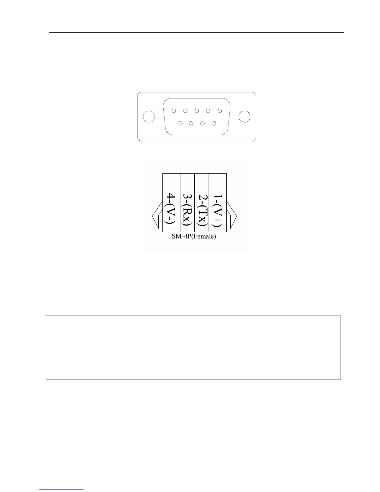
3.2.4 Communication Port
A 4pin connector to RS232 port is provided to communicate with host computer for calibration and
configuration.
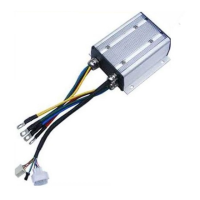
Figure 7: RS232 Interface on 4pin connector to RS232 converter
Figure 8
:
SM-4P connector for communication interface on KLS-D controller
3.3 Installation Check List
Before operating the vehicle, complete the following checkout procedure. Use LED code as
a reference as listed in Table 1.
Caution:
• Put the vehicle up on blocks to get the drive wheels off the ground before beginning these
tests.
• Do not allow anyone to stand directly in front of or behind the vehicle during the checkout.
• Make sure the PWR switch and the brake is off
• Use well-insulated tools.
• Make sure the wire is connected correctly
• Turn the PWR switch on.
• The fault code will be detected automatically at restart.