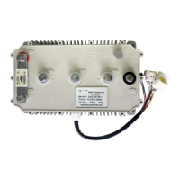
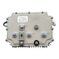
Kelly Jaguar series KLS-N Sinusoidal Brushless PM Motor Controller User’s Manual V2.9
(33)CAN-H:Greenish(Optional function)
(7) PWR: Controller power supply (input). Pink
(34)CAN-L:Brownish(Optional function)
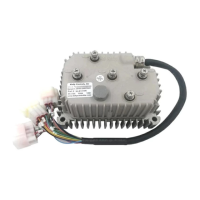
DJ7091Y-2.3-21 Pin Definition
(15) Micro_SW: Throttle switch input. Gray
(3) Throttle: Throttle analog input, 0-5V. Dark Green
(20) RTN: Signal return. Black
(8) Meter: Copy signal of hall sensors. Dark Gray
(4) 5V: 5V supply output, <40mA. Purple
(2) Brake_AN:Brake variable regen or Boost function. Brown
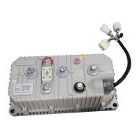
DJ7061Y-2.3-21 Pin Definition
(21) RTN:Signal return. Black
(1) Temp: Motor temperature sensor input. Raddle.
(5) 5V: 5V supply output,<40mA.Purple
(18) Hall A: Hall phase A. Yellow
(17) Hall B: Hall phase B. Dark Green
(16) Hall C: Hall phase C. Dark Blue
Notes:
1. All RTN pins are internally connected.
2. Meter function is to copy either of hall sensors.
3. Switch to 12V is active. Open switch is inactive.
4. F-N-R control and three speed function can not be used at the same time.They both
used the same pin as pin12=FWD
Caution:
• Do not apply power until you are certain the controller wiring is correct and has been
double checked. Wiring faults will damage the controller.
• Ensure that the B- wiring is securely and properly connected before applying power.
• The preferred connection of the system contactor or circuit breaker is in series with the B+
line.
• All contactors or circuit breakers in the B+ line must have precharge resistors across their
contacts. Lack of even one of these precharge resistors may severely damage the controller
at switch-on.


 To Next Page