EasyManuals Logo

Kelly KLS7240ND User Manual

Kelly KLS7240ND
37 pages
To Next Page IconTo Next Page
To Previous Page IconTo Previous Page
Page #8 background imageLoading...
Page #8 background image
Kelly KLS-N Sinusoidal Brushless Permanent Magnet Motor Controller Users Manual V2.9
6
KLS7215N
48-72V
200A
60A
KLS7218N
48-72V
220A
80A
KLS7222N
48-72V
250A
85A
KLS7230N
48-72V
280A
90A
KLS7230ND
48-72V
280A
Up to 150A *
KLS7235ND
48-72V
320A
Up to 165A *
Note: *Depends on conductive heat sink
**Peak current can be prolonged with additional heat sink, easily over 2 minutes.
Kelly KLS-N - Sinusoidal Brushless Permanent Magnet Motor Controller
Model
Nominal
Voltage
Peak Current
2 Minutes
Continuous
Current
KLS4860NG
36-48V
400A
160A-240A
KLS4875NC
36-48V
500A
200A-300A
KLS48100NC
36-48V
600A
240A-360A
KLS48120NC
36-48V
700A
280A-420A
KLS7260NG
48-72V
400A
160A-240A
KLS7275NC
48-72V
500A
200A-300A
KLS72100NC
48-72V
600A
240A-360A
KLS72120NC
48-72V
700A
280A-420A
Chapter 3 Wiring and Installation
3.1 Mounting the Controller
The controller can be oriented in any position which should be as clean and dry as possible,
and if necessary, shielded with a cover to protect it from water and contaminants.
To ensure full rated output power, the controller should be fastened to a clean, flat metal
surface with four screws. Applying silicon grease or some other thermal conductive material to
contact surface will enhance thermal performance.
Proper heat sinking and airflow are vital to achieve the full power capability of the controller.
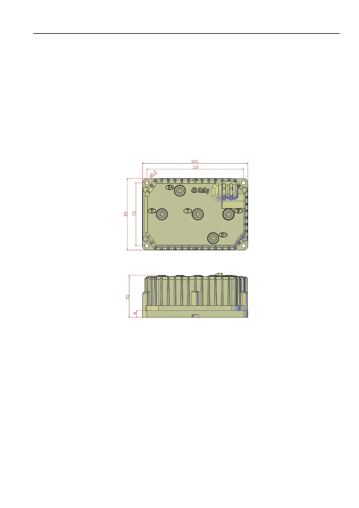
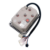
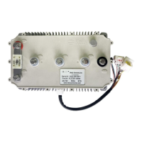
The case outline and mounting holes dimensions are shown below.

Questions and Answers:

Question and Answer IconNeed help?

Do you have a question about the Kelly KLS7240ND and is the answer not in the manual?

Kelly KLS7240ND Specifications

General IconGeneral
BrandKelly
ModelKLS7240ND
CategoryController
LanguageEnglish

Related product manuals