Kelly KLS8080I/IPS Sinusoidal Brushless Motor Controller User’s Manual V 1.10
3.2.3 Optional wiring of KLS8080I/IPS controller
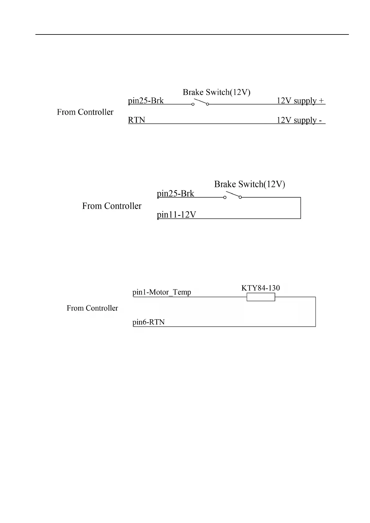
The 12V input signal of the pin supplies the second braking function of the controller.
Figure 5: Wiring of brake switch(12V): 12V is provided by external source.
Figure 6: Wiring of brake switch(12V): 12V is provided by KLS8080I controller on pin11
Figure 7: Wiring diagram for motor temperature sensor
NOTE:The motor temperature sensor and brake switch used the same I/O port on pin1.Both
functions can not be used at the same time.KLS controller can support KTY84-150 and
KTY84-130 thermistors.


 To Next Page