Do you have a question about the Kemppi KEMPACT 323A and is the answer not in the manual?
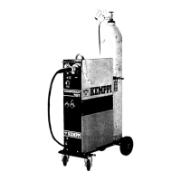
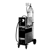
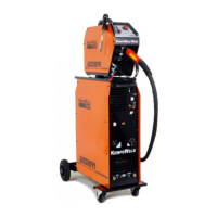
Detailed specifications and parameters for various Kempact welding machine models.
Schematics illustrating the main circuit configurations of the welding machines.
Overview and function of key machine components and parts.
Circuit diagram for Kempact 181 and 251 welding machine models.
Circuit diagram for Kempact 253 and 323 welding machine models.
Circuit diagram for Kempact 253MV and 323MV welding machine models.
Details and connectors for the main circuit card in Kempact 181/251.
Details and connectors for the main circuit card in Kempact 253/323.
Details and connectors for the main circuit card in Kempact 253MV/323MV.
Connector pin assignments for the secondary rectifier card Z002.
Explanation of LEDs on the control card for status indication.
Connector pin assignments for the control card A001.
Connector pin assignments for the panel card P001.
Measurement and testing procedures for Kempact 181 and 251 models.
Measurement and testing procedures for Kempact 253 and 323 models.
Measurement and testing procedures for Kempact 253MV and 323MV models.
Testing procedures for the secondary rectifier card Z002.
Testing procedures for PTC components and overheat protection.
Procedures for verifying control card A001 voltages using LEDs.
Installation instructions for the main circuit card Z001 and its components.
Installation instructions for the secondary rectifier card Z002 and its components.
Installation instructions for other major components like transformers and chokes.
| Brand | Kemppi |
|---|---|
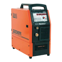
| Model | KEMPACT 323A |
| Category | Welding System |
| Language | English |