EasyManua.ls Logo

Kemppi MasterTig 2800 User Manual

Kemppi MasterTig 2800
31 pages
To Next Page IconTo Next Page
Page #1 background imageLoading...
Page #1 background image
Service manual
Ver. 1.0
1400
1500
2200
2800
3500
1500
2200
2800
3500

Questions and Answers:

Kemppi MasterTig 2800 Specifications

General IconGeneral
Output Current Range (TIG)5 - 280 A
Output Current Range (MMA)10 - 280 A
Output 40 °C TIG (35% Duty Cycle)280 A
Welding current range MMA10 - 280 A
Welding current range TIG5 A - 280 A
Protection ClassIP23
StandardsIEC 60974-1, IEC 60974-10

Summary

Machine Specifications

Master 1400 Specifications

Technical specifications, switches, and connectors for the Master 1400 welding machine.

Master 1500 Specifications

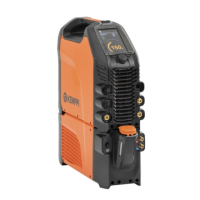
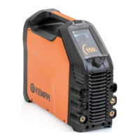
Technical specifications, switches, and connectors for the Master 1500 welding machine.

Master 2200 Specifications

Technical specifications, switches, and connectors for the Master 2200 welding machine.

Master 2800 and 3500 Specifications

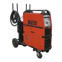
Technical specifications, switches, and connectors for the Master 2800 and 3500 welding machines.

Operator Interface and Controls

Mastertig 1500/2200 Pulse Panel Controls

Details the functions and settings of the pulse panel for Mastertig 1500 and 2200 models.

Minilog Panel Functions

Explains the operation and adjustments available on the Minilog panel.

Mastertig 2800/3500 Pulse Panel Controls

Details the functions and settings of the pulse panel for Mastertig 2800 and 3500 models.

Minilog Panel Functions

Explains the operation and adjustments available on the Minilog panel.

Technical Operation and Principles

Welding Power Source Operation Principle

Describes the half-bridge operation using IGBT transistors and PWM control.

IGBT Gate Pulse Waveforms (2800/3500)

Illustrates IGBT gate pulse measurements at minimum and maximum power.

IGBT Gate Pulse Waveforms (1400/1500/2200)

Illustrates IGBT gate pulse measurements at minimum and maximum power.

Troubleshooting

Troubleshooting Common Issues

Guides users through diagnosing and resolving common power source malfunctions.

Control Cards and System Details

Control Card A001 Block Diagram

Explains the architecture and functions of the main control card A001.

Control Card Signal Connections

Details signal interconnections between control cards A001, A002, and A004.

Control Card A001 Functional Testing

Procedures for testing the functionality of Control Card A001.

Important Notes

Related product manuals