CO
2
Incubator HERAcell
®
150 Operating Instructions
71
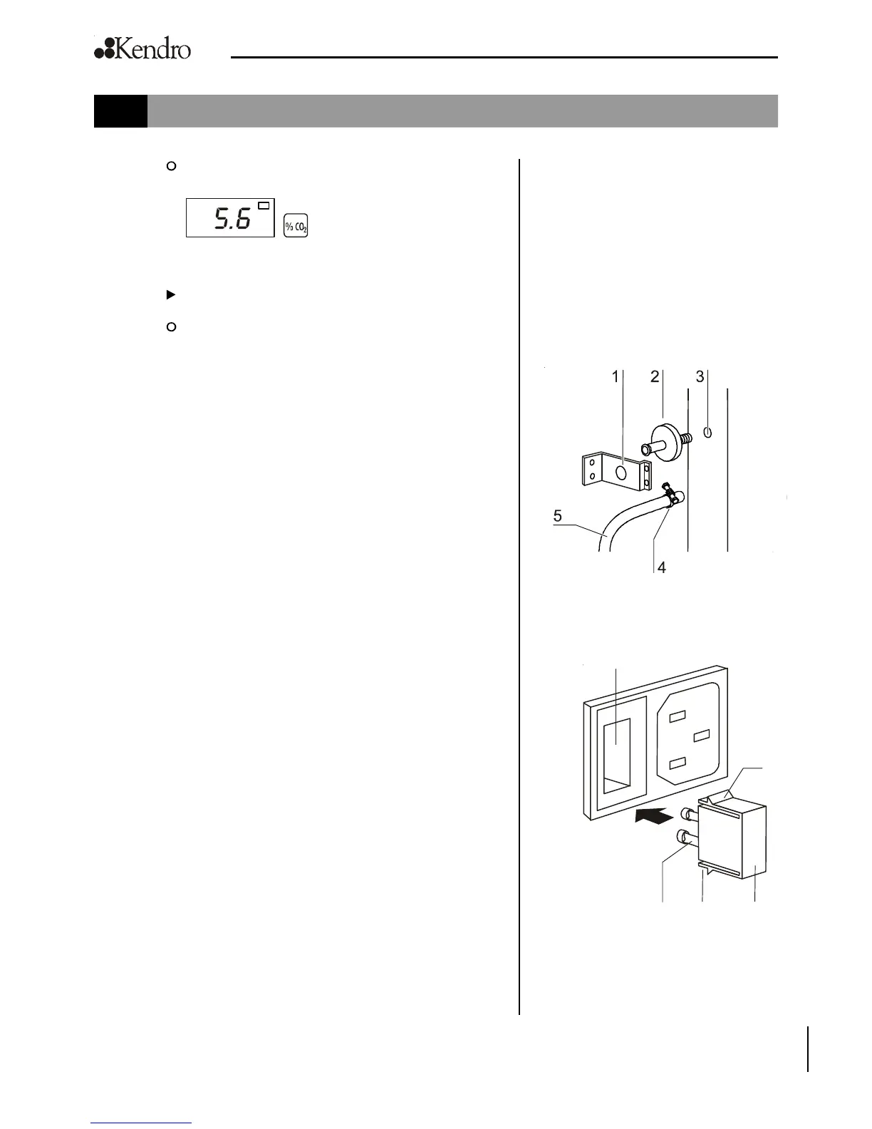
Fig. 30
Sterile filter replacement
Fig. 31
Device fuse replacement
10. Maintenance
then the corrected actual value (measured destinati-
on value 5.6 %) is displayed.
5. Cancel the calibration process:
Press any key.
The temperature display and the CO
2
display show
the actual values.
10.7 Replacing the sterile filters
The sterile filters (CO
2
/O
2
/N
2
supply and auto-zero air inlet)
have plastic threads and are screwed by hand into the threaded
hole at the control box.
Procedure for gas supply sterile filter:
1. Make sure that the gas supply is shut off.
2. Fig. 30: Loosen hose clamp [4].
3. Remove gas hose [5] from sterile filter sleeve [2].
Procedure for all sterile filters:
4. Remove retainer [1].
5. Unscrew sterile filter [2] from the threaded hole [3].
6. When installing the new sterile filter, make sure that the
plastic thread is not canted. Screw filter in carefully all the
way to the stop.
7. Install retainer [1].
Procedure for gas supply sterile filter:
8. Connect gas hose to sterile filter sleeve and secure it using
hose clamp. Check to see if the gas hose is securely seated
on the sleeve.
10.8 Replacing the device fuses
Fig. 31: The two identical device fuses [4] are installed in the
fuse compartment [1] next to the power plug receptacle of the
device:
• Time delay fuses, 6.3 A ( 5x20 mm)
1. The fuse holder is secured to the fuse compartment [1] using
two locking tabs [2].
2. To remove the fuse holder, squeeze the two locking tabs
and pull holder [3] out of fuse compartment.
3. Remove faulty fuse from holder and install new fuse.
4. Slide fuse holder into fuse compartment and press holder
on until locking tabs are fully engaged.
1
2
4 32
 Loading...