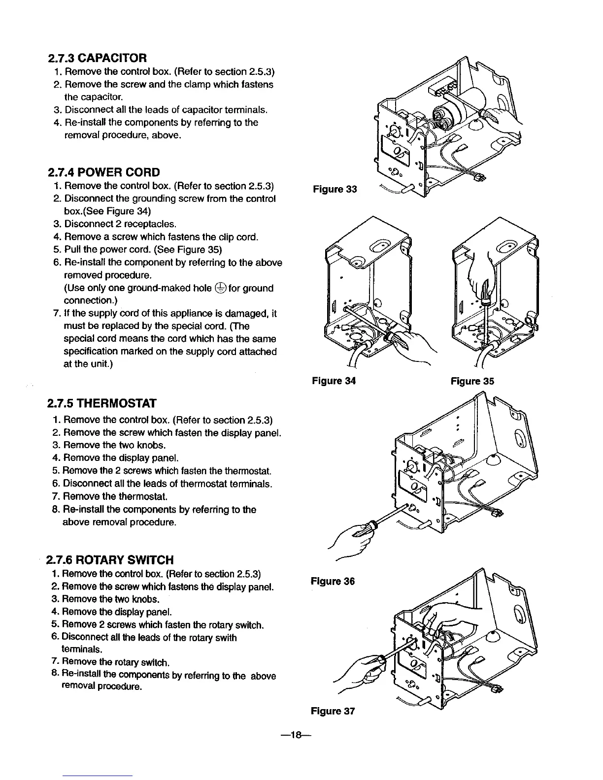
2.7.3 CAPACITOR
1. Remove the control box. (Refer to section 2.5.3)
2. Remove the screw and the clamp which fastens
the capacitor.
3. Disconnect all the leads of capacitor terminals.
4. Re-instan the components by referring to the
removal procedure, above.
2.7.4 POWER CORD
1. Remove the control box. (Refer to section 2.5.3)
2. Disconnect the grounding screw from the control
box.(See Figure 34)
3. Disconnect 2 receptacles.
4. Remove a screw which fastens the clip cord.
5. Pull the power cord. (See Figure 35)
6. Re-install the component by referring to the above
removed procedure.
(Use only one ground-maked hole (_ for ground
connection.)
7. If the supply cord of this appliance is damaged, it
must be replaced by the special cord. (The
special cord means the cordwhich has the same
specification marked on the supply cord attached
at the unit.)
2.7.5 THERMOSTAT
1. Remove the control box. (Refer to section 2.5.3)
2. Remove the screw which fasten the display panel.
3. Remove the two knobs.
4. Remove the display panel.
5. Remove the 2 screws whichfasten the thermostat.
6. Disconnect all the leads of thermostat terminals.
7. Remove the thermostat.
8. Re-install the components by referring to the
above removal procedure.
Figure 33
Figure 34
Figure 35
2.7.6 ROTARY SWITCH
1. Remove the controlbox. (Refer to section2.5.3)
2. Remove the screw whichfastensthe display panel.
3. Remove the two knobs.
4. Remove the displaypanel.
5. Remove 2 screwswhichfastenthe rotaryswitch.
6. Disconnectall the leads ofthe rotaryswith
terminals.
7. Remove the rotaWswitch.
8. Re-installthe componentsby referringto the above
removal procedure.
Figure 36
Figure 37
m18--