• MODEL: 79122
-- Before the following disassembly, POWER SWITCH is set to OFF and disconnect the power cord.
2.9 MECHANICAL PARTS
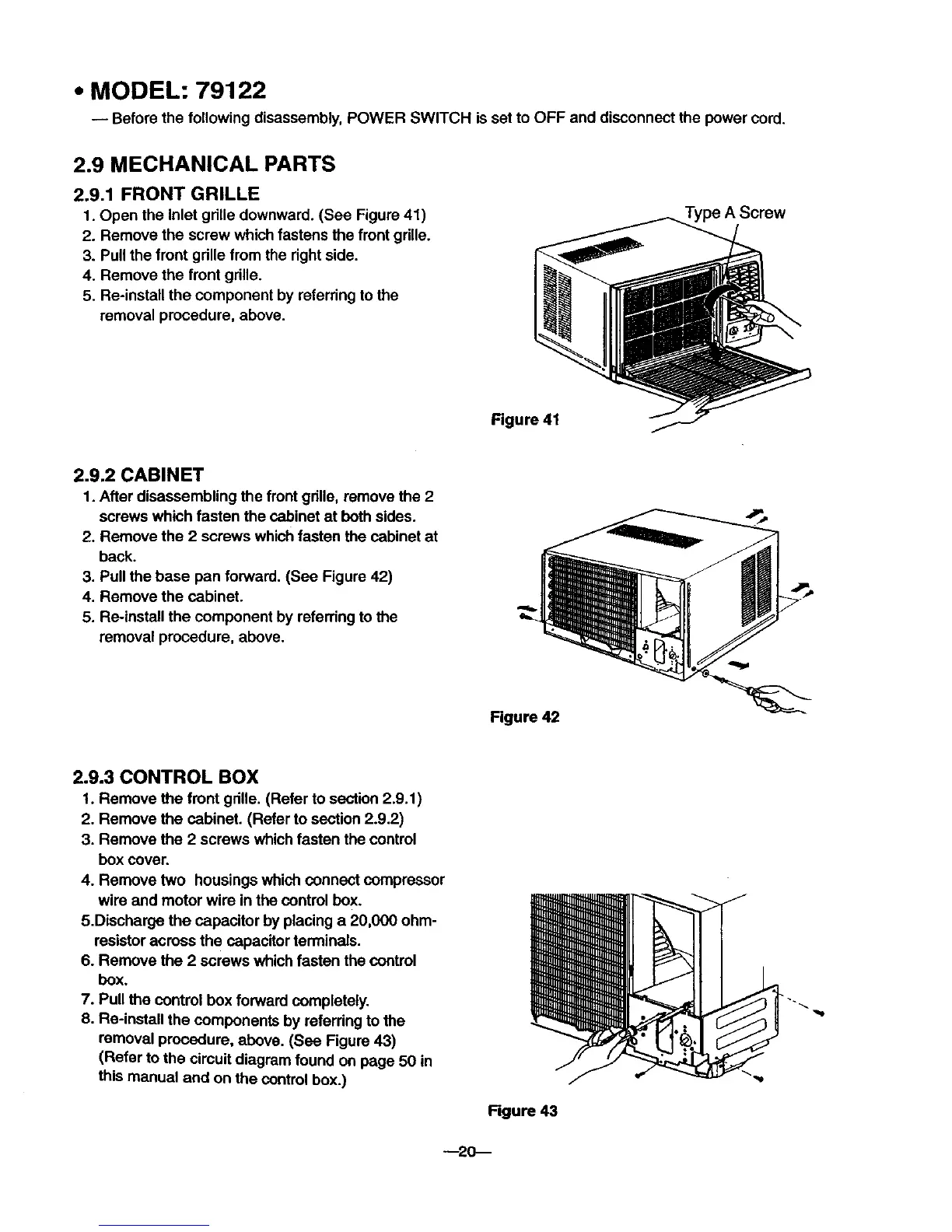
2.9,1 FRONT GRILLE
1. Open the inlet gdlle downward. (See Figure 41)
2. Remove the screw which fastens the front gdlle.
3. Pull the front gdlle from the right side.
4. Remove the front gdlle.
5. Re-install the component by referring to the
removal procedure, above.
Type A Screw
Figure 41
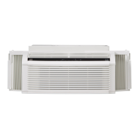
2.9.2 CABINET
1. After disassembling the frontgdlle, remove the 2
screws which fasten the cabinet at both sides.
2. Remove the 2 screws which fasten the cabinet at
back.
3. Pull the base pan forward. (See Figure 42)
4. Remove the cabinet.
5. Re-install the component by referring to the
removal procedure, above.
Figure 42
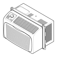
2.9.3 CONTROL BOX
1. Remove the front gdlle. (Refer to section 2.9.1 )
2. Remove the cabinet. (Refer to section 2.9.2)
3. Remove the 2 screws which fasten the control
box cover.
4. Remove two housings which connect compressor
wire and motor wire in the control box.
5.Discharge the capacitor by placing a 20,000 ohm-
resistor across the capacitor terminals.
6. Remove the 2 screws which fasten the control
box.
7. Pull the control box forward completely.
8. Re-install the components by referring to the
removal procedure, above. (See Figure 43)
(Refer to the circuit diagram found on page 50 in
this manual and on the control box.)
Rgure 43
--20--