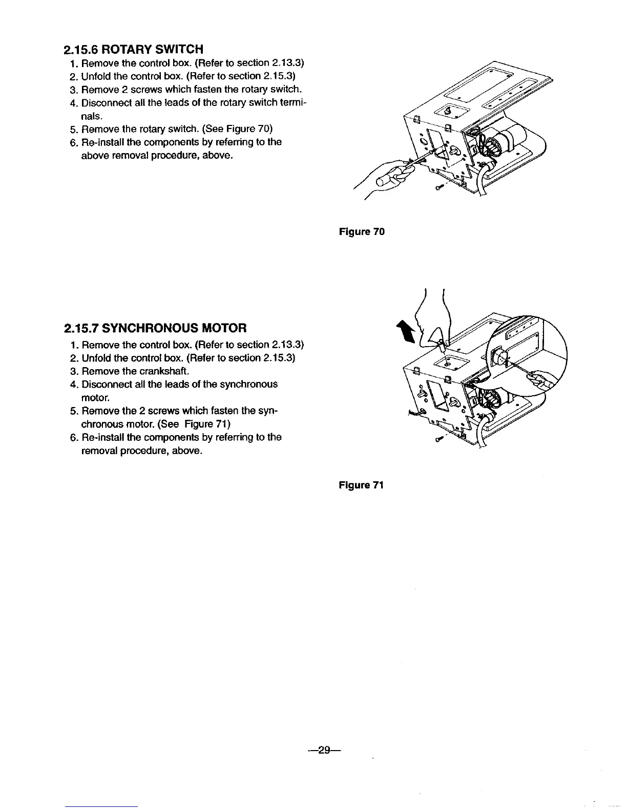
2.1 5.6 ROTARY SWITCH
1. Remove the control box. (Refer to section 2.13.3)
2. Unfold the control box. (Refer to section 2.15.3)
3. Remove 2 screws which fasten the rotary switch.
4. Disconnect all the leads of the rotary switch termi-
nals.
5. Remove the rotary switch. (See Figure 70)
6. Re-install the components by referring to the
above removal procedure, above.
Figure 70
2.15.7 SYNCHRONOUS MOTOR
1. Remove the control box. (Refer to section 2.13.3)
2. Unfold the controlbox. (Refer to section 2.15.3)
3. Remove the crankshaft.
4. Disconnect all the leads of the synchronous
motor.
5. Remove the 2 screws which fasten the syn-
chronous motor. (See Figure 71)
6. Re-install the components by referring to the
removal procedure, above.
Figure 71
--29--