Installation Instructions
EXTERNAL EXHAUST DUCTING
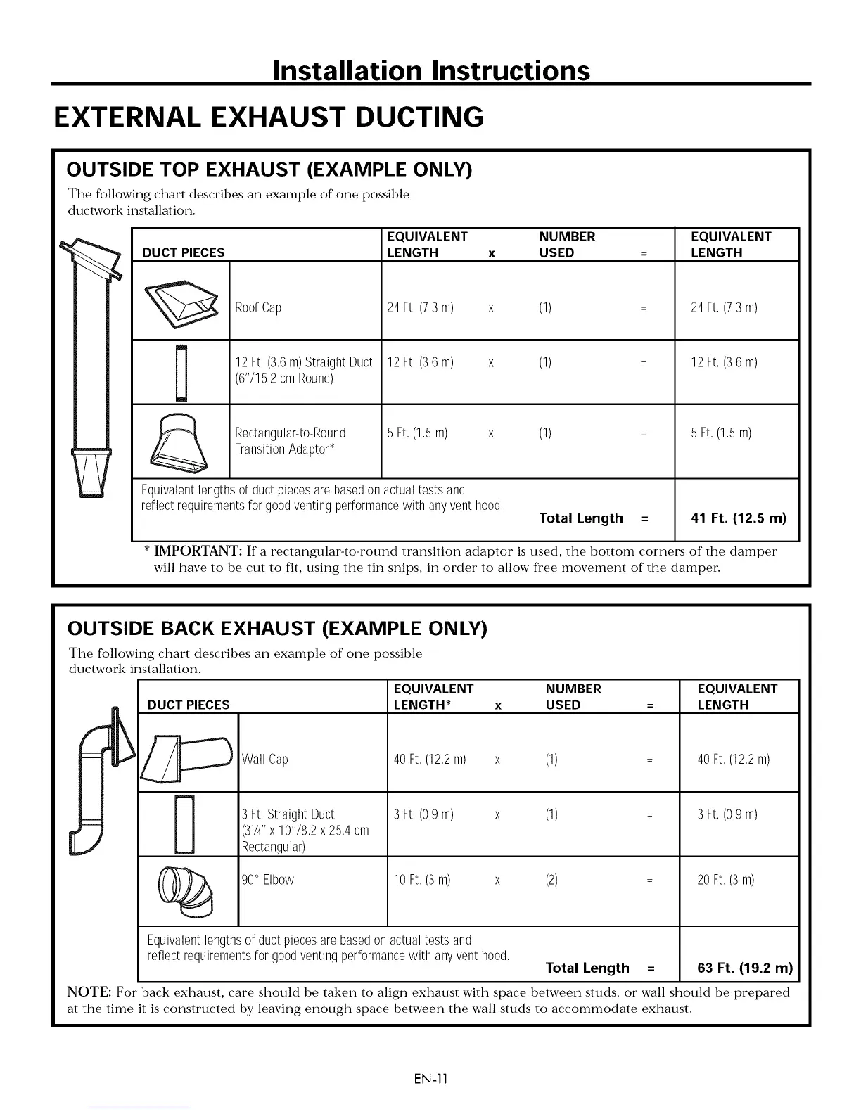
OUTSIDE TOP EXHAUST (EXAMPLE ONLY)
The following chart describes an example of one possible
ductwork installation.
DUCT PIECES
Roof Cap
12Ft, (3,6m)StraightDuct
(6'715,2cmRound)
Rectangular-to-Round
TransitionAdaptor*
EQUIVALENT NUMBER EQUIVALENT
LENGTH x USED = LENGTH
24Ft, (7,3m) x (1)
12 Ft,(3,6m) x (1)
5 Ft, (1,5m) x (1)
Equivalentlengthsofductpiecesarebasedonactualtestsand
reflectrequirementsfor goodventingperformancewith anyvent hood,
Total Length =
24Ft, (7,3m)
12 Ft,(3,6m)
5 Ft, (1,5m)
41 Ft. (12.5 m)
* IMPORTANT: If a rectangular-to-round transition adaptor is used, the bottom corners of the damper
will have to be cut to fit, using the tin snips, in order to allow fi'ee movement of the damper
OUTSIDE BACK EXHAUST (EXAMPLE ONLY)
The following chart describes an example of one possible
ductwork installation.
DUCT PIECES
Wall Cap
3Ft, StraightDuct
(31/4"x 10'78,2x25,4cm
Rectangular)
90° Elbow
EQUIVALENT NUMBER EQUIVALENT
LENGTH* x USED = LENGTH
40Ft,(12,2m) x (1)
3Ft, (0,9m) x (1)
10Ft,(3 m) x (2)
40Ft,(12,2m)
3Ft, (0,9m)
20Ft,(3 m)
Equivalentlengthsof ductpiecesarebasedonactualtests and
reflectrequirementsfor goodventingperformancewith anyventhood,
Total Length = 63 Ft. (19.2 m)
NOTE: For- back exhaust, care should be taken to align exhaust with space between studs, or wall should be prepared
at the time it is constructed by leaving enough space between the wall studs to accommodate exhaust.
EN-11