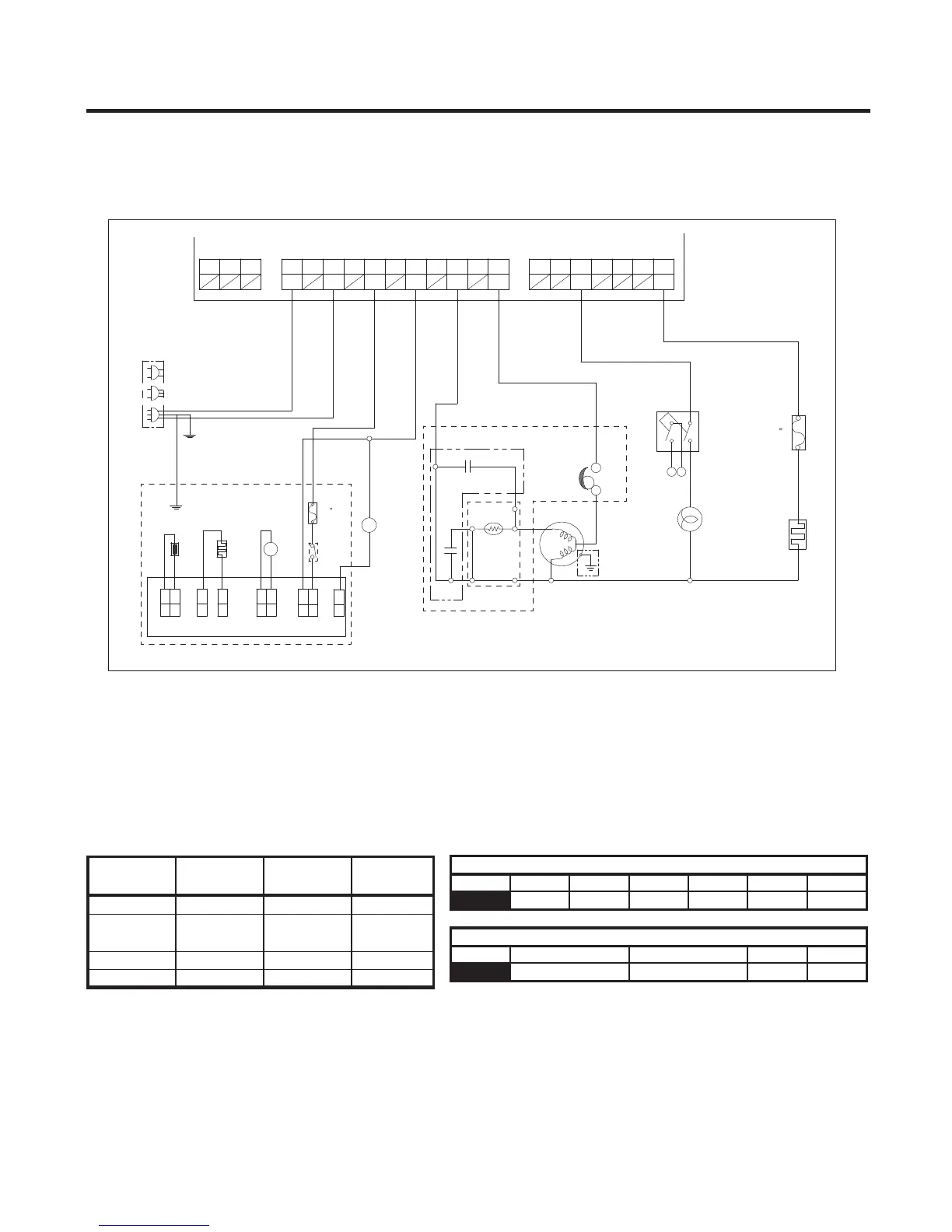
8-2-1 Power Circuit
Power is supplied to the control board at the pin 11 and 9 of connector #1. (Refer to figure 1)
11 10
9 8 7 6 5 4 3 2 1 5 6 71 2 3 4
123
CON3
CON1 CON2
SB
BK
BN
BLYLBNSB BL
GN/YL
PK
CAPACITOR PART
WH
1
1
CON4
MOTOR
1
WH
2
ICE MAKER
CON3
WH
2
CON5
1
SHEATH
ICE SENSOR
WH
MM
BK
CON1
WH
HEATER,
CON2
Cs
3
2
RD
2
6
BK
1
S/W
CON6
P.T.C
BK
5
Cr
BL
POWER
4
RD
1
BL
I/MAKER W/VALVE
FUSE-M
(GN)
(98 C)
BK
FUSE-M
BL
OLP
PART
COMP' EARTH
(72 C)
GN
BL
HEATER
RD
(GN)
BL
R-LAMP
/YL
M
S
PWB (PCB) ASSEMBLY, ICE MAKER
ICE MAKER PART
POWER
SUPPLY
L
N
CORD
VV
SHEATH
com
nc
nc
com
DOOR S/W-R
AA
BB
SB BN YL BL BL BK
SB BN
(GN)
GN/YL
COMP' ACCESSORIES
FIGURE 1
8-2-2 Load and Door Light Circuit (HV)
1. Load Drive Condition Check
To measure outputs of the control board, check voltages between the pins for the following components:
(Refer to figure 1)
PIN 11 9 7 5 3 1
N L1
L(I/M)
N(I/M)
N COMP
PIN 5 7
N/C DEF-HTRN/C DOOR LAMP
CONNECTOR 1
CONNECTOR 2
1 3
NOTE: When the door of the refrigerator is left open for 7 minutes or longer, the lamp of the refrigerator turns off automatically.
- 30 -
Circuit
Pin
Number
Pin
Number
Output
Voltage
Compressor Con 1 Pin 1 Con 1 Pin 3 115 VAC
Defrost
Heater Con 2 Pin 7 Con 1 Pin 3 115 VAC
R LAMP Con 2 Pin 3 Con 1 Pin 3 115 VAC
Ice Maker
Con 1 Pin 7 Con 1 Pin 5 115 VAC