466724112 • 19
7
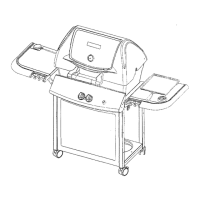
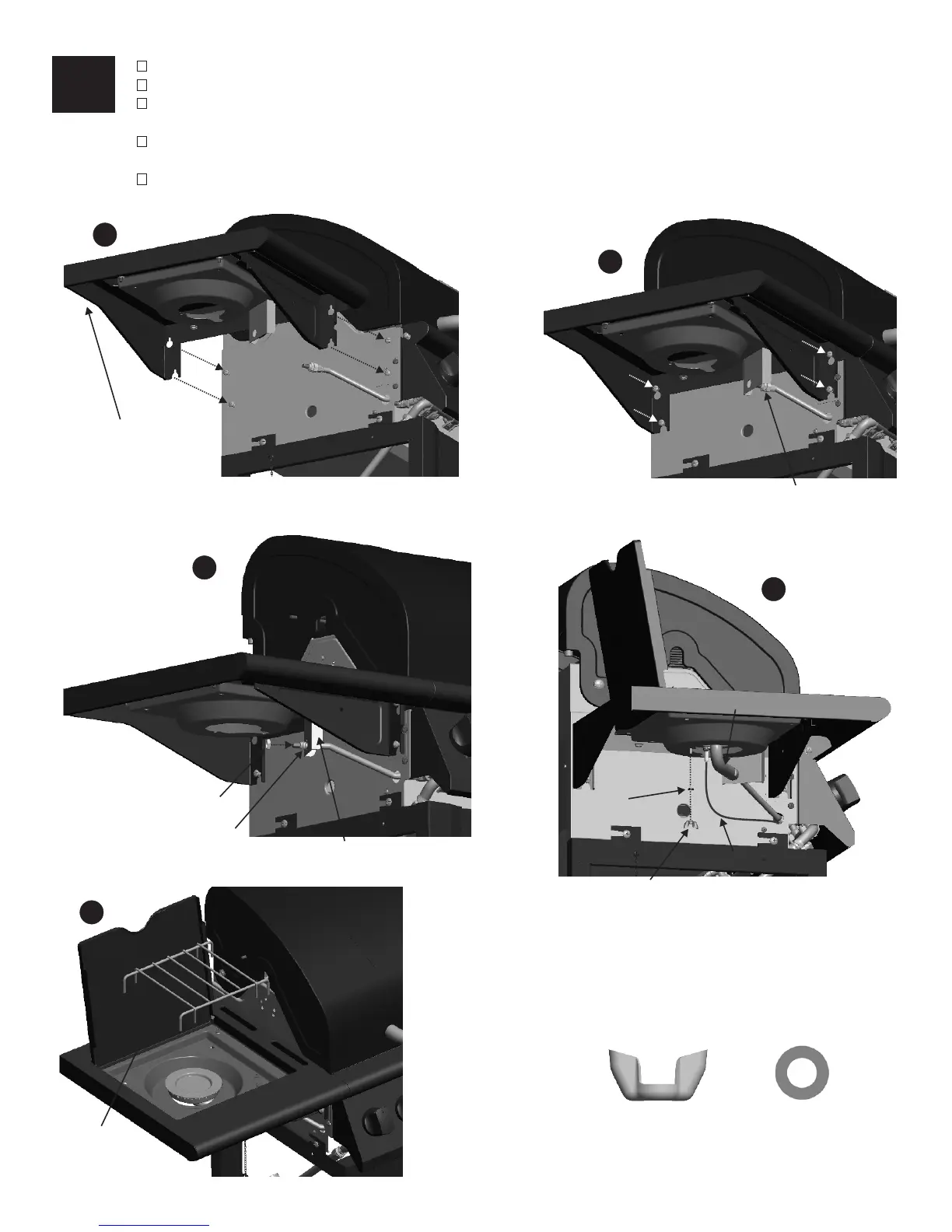
Correctly assembled burner-to-valve engagement
Qty: 1
Wing Nut
Qty: 1
5mm Flat Washer
Side burner T
u
b
e
Ignitor Wire
A
Left side shelf
Injecter
Injecter
Nut
Side burner Brace
B
C
D
E
Wing Nut
5mm
Flat Washer
Side burner
Grate
Slide keyhole slots in the left side shelf over the five pre-installed screws on the left side of the firebox (A).
. Attach side burner ignitor wire to electrode as shown (D).
Place grate onto side burner shelf (E).
Tighten the pre-installed screws (B).
Remove the nut from injector, insert the injector to the hole on the side burner brace, re-install and tighten the
nut to fix the injector to side burner brace (C).
Place side burner into shelf. Make sure injector is inside side burner tube. Attach side burner to drip pan with
(1) flat washer and wing nut