Do you have a question about the Kenwood 941 and is the answer not in the manual?
| Supply Voltage | 13.8 VDC |
|---|---|
| Modes | CW, AM, FM |
| RF Power Output | 100 W (PEP) |
| Receiver Sensitivity | 0.5 μV (10 dB S/N) |
| Sensitivity | 0.5 μV (10 dB S/N) |
| Power Supply | 13.8 V DC |
Outlines manual scope, parts ordering, personnel safety, and FCC compliance.
Covers unpacking, licensing requirements, and pre-installation checkout procedures.
Guides on vehicle inspection, antenna placement, radio mounting, and DC power wiring.
Details service information and planning for control station antenna systems and radio location.
Illustrates the setup process for signaling, external speakers, and programming.
Summarizes general, trunked, and conventional transceiver features.
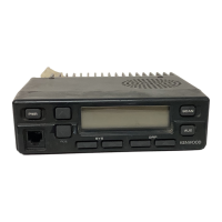
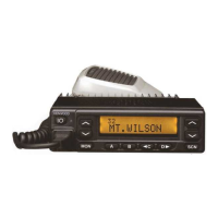
Explains the functions of front panel keys like Power, System, Group, and Scan.
Details the function of the AUX key and its programmable auxiliary features.
Describes the system display, group display, and various indicators on the front panel.
Details system scan operation, system lockout methods, and scan timing parameters.
Covers drop-out delay time and dwell time for scan resume.
Details system/group revert options, scan message wait, and call indicator functions.
Explains priority ID code hierarchy and group scan operation.
Covers free system ringback, system search, transpond, and talk-around features.
Explains preferred system revert assignment and alphanumeric display selection.
Details the AUTO TEL feature and describes audible feedback tones.
Explains clear-to-talk modes (ON/OFF) and their operational differences.
Covers conventional system operations and the functions of the KDD-4 external decoder.
Covers horn alert settings and system scan types (fixed and list).
Lists terminal functions for external equipment via KCT-19.
Details the necessary hardware and software for transceiver programming.
Explains clone mode operation and describes dealer mode.
Describes how to enter dealer mode and use the SYSTEM key.
Details controls within dealer mode and the procedure for panel tuning.
Guides the assembly and preparation of the KDD-4 DTMF decoder.
Details the physical installation of the KDD-4 into the transceiver's TX-RX unit.
Covers KDD-4 jumper configuration and KCT-19 accessory cable installation.
Lists the pin assignments and functions for the KCT-19 accessory cable.
Explains the connection and modification for the KCT-18 ignition sense cable.
Provides connection procedures for external speakers KES-3 and KES-4.
Describes how to mount the control panel in an upside-down configuration.
Illustrates the principal functional blocks of the TK-940/941 transceiver.
Shows block diagrams for TX-RX unit and LCD assembly.
Illustrates signal levels within the TK-940 receiver and transmitter circuits.
Illustrates signal levels within the TK-941 receiver and transmitter circuits.
Describes the transceiver's receiving system, including RF and IF units.
Details the audio amplifier unit and the squelch circuit operation.
Explains the microphone amplifier, final amplifier, and APC circuit.
Describes the PLL system, including VCXO, VCO, and PLL unlock detection.
Outlines the control unit's CPU functions, memory, and data converters.
Describes PLL data output, horn control logic, and power supply circuit.
Details the CPU, power switch circuit, and tone generator in the LCD assembly.
Provides block diagrams and terminal connections for Level Adjuster (IC6) and Audio Amplifier (IC11).
Shows terminal connections and block diagram for the AT24C02N EEPROM.
Lists the terminal functions for the 78312AGF3563BE microprocessor (IC209).
Lists the terminal functions for the 75308BGK740BE9 microprocessor in the LCD assembly.
Details terminal connections and block diagram for the PLL/VCO IC1.
Lists components for the TX-RX Unit, their part numbers, and functions.
Lists components for PLL/VCO and LCD Assy, including part numbers and functions.
Details specifications for capacitors and resistors, including types and values.
Lists general parts such as cabinets, chassis, labels, and cables for the transceiver.
Lists specific parts for the TX-RX Unit, categorized by model.
Continues the list of parts for the TX-RX Unit.
Continues the list of parts for the TX-RX Unit.
Continues the list of parts for the TX-RX Unit.
Continues the list of parts for the TX-RX Unit.
Continues the list of parts for the TX-RX Unit.
Continues the list of parts for the TX-RX Unit.
Continues the list of parts for the TX-RX Unit.
Continues the list of parts for the TX-RX Unit.
Lists parts for the PLL/VCO unit.
Continues the list of parts for the PLL/VCO unit.
Continues the list of parts for the PLL/VCO unit.
Lists parts for the LCD Assy.
Continues the list of parts for the LCD Assy.
Provides a visual breakdown of the transceiver's components and their assembly order.
Illustrates the steps and components used for packing the transceiver for shipment.
Lists required test equipment and details the MIC connector pinout and test cables.
Explains switch functions, LCD indicators, and user, dealer, tuning modes.
Explains the different operating modes for adjustment (User, Dealer, Tuning).
Details adjustment procedures for memory frequency, signaling, receiver, and transmitter.
Details the operational steps for dealer and tuning modes.
Guides on sensitivity and squelch adjustments for the receiver section.
Covers adjustments for frequency, maximum power output, and modulation balance.
Details adjustments for QT deviation, DQT deviation, and fine LTR settings.
Lists terminal functions for the TX-RX unit's various sections.
Details terminal functions for display, PLL/VCO, and LCD Assy sections.
Lists general, receiver, transmitter, and environmental specifications for the transceiver.
Overviews of accessories/software and KENWOOD worldwide contact information.
Shows the component and foil side layouts for the PLL/VCO circuit board.
Displays component and foil side layouts for the TX-RX Unit (B/2).
Continues the component and foil side layouts for the TX-RX Unit (B/2).
Continues the component and foil side layouts for the TX-RX Unit (B/2).
Shows the component side layout for the TX-RX Unit (A/2).
Displays component and foil side layouts for the TX-RX Unit (A/2).
Continues the component and foil side layouts for the TX-RX Unit (A/2).
Continues the component and foil side layouts for the TX-RX Unit (A/2).
Continues the component and foil side layouts for the TX-RX Unit (A/2).
Continues the component and foil side layouts for the TX-RX Unit (A/2).
Continues the component and foil side layouts for the TX-RX Unit (A/2).
Continues the component and foil side layouts for the TX-RX Unit (A/2).
Presents the schematic diagrams for the TX-RX Unit (A/2).
Continues the schematic diagram for the TX-RX Unit (A/2).
Continues the schematic diagram for the TX-RX Unit (A/2).
Shows the schematic diagram for the TX-RX Unit control section (B/2).
Continues the schematic diagram for the TX-RX Unit control section (B/2).
Continues the schematic diagram for the TX-RX Unit control section (B/2).