4
|
DNX7220
Connection
PRK SW
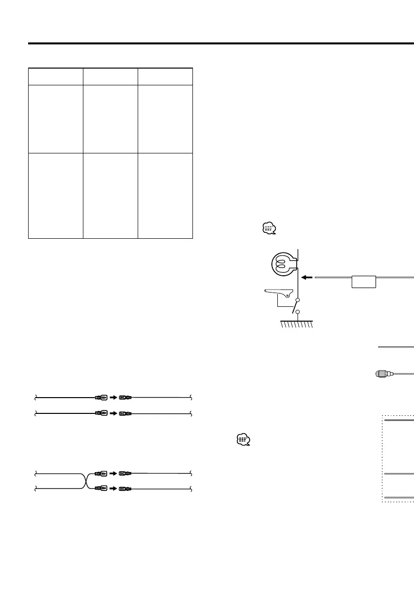
For the sake of safety,
be sure to connect the
parking sensor.
Connect to the vehicle's parking brake
detection switch harness using the
supplied relay connector.
To steering remote
To use the steering wheel remote control feature,
you need to an exclusive remote adapter (not
supplied) matches your car is required.
When this terminal is not in use, leave its cap on.
Connect to the terminal that is grounded when either
the telephone rings or during conversation.
To "EXT.AMP.CONT." terminal of the amplifier
having the external amp control function.
Connect to vehicle's reverse lamp harness
when using the optional rear view camera.
To connect the Kenwood navigation system,
consult your navigation manual.
Connect either to the power control terminal when
using the optional power amplifier, or to the antenna
control terminal in the vehicle.
Connector Function Guide
Pin Numbers for
ISO Connectors
Cable Colour Functions
External Power
Connector
A-4 Yellow Battery
A-5 Blue/White Power Control
A-6 Orange/White Dimmer
A-7 Red Ignition (ACC)
A-8 Black Earth (Ground)
Connection
Speaker
Connector
B-1 Purple Rear Right (+)
B-2 Purple/Black Rear Right (–)
B-3 Gray Front Right (+)
B-4 Gray/Black Front Right (–)
B-5 White Front Left (+)
B-6 White/Black Front Left (–)
B-7 Green Rear Left (+)
B-8 Green/Black Rear Left (–)
2WARNING
Connecting the ISO Connector
The pin arrangement for the ISO connectors depends on
the type of vehicle you drive. Make sure to make the proper
connections to prevent damage to the unit.
The default connection for the wiring harness is described in
1 below. If the ISO connector pins are set as described in 2,
make the connection as illustrated.
Please be sure to reconnect the cable as shown 2 below to
install this unit to the Volkswagen vehicles etc.
1 (Default setting) The A-7 pin (red) of the vehicle’s
ISO connector is linked with the ignition, and the A-
4 pin (yellow) is connected to the constant power
supply.
Unit Vehicle
A-7 Pin (Red)
A-4 Pin (Yellow)
Ignition cable (Red)
Battery cable (Yellow)
2 The A-7 pin (red) of the vehicle’s ISO connector is
connected to the constant power supply, and the
A-4 pin (yellow) is linked to the ignition.
Unit Vehicle
A-7 Pin (Red)
A-4 Pin (Yellow)
Ignition cable
(Red)
Battery cable
(Yellow)
DNXDDX7instaEEnr1.indd4DNXDDX7instaEEnr1.indd4 08.1.311:39:44PM08.1.311:39:44PM
 Loading...