Do you have a question about the Kenwood KAC-6402 and is the answer not in the manual?
Details for recording serial number and model information for future reference.
Key safety warnings and precautions to prevent injury, fire, or damage.
Instructions for safely cleaning the amplifier's front panel using appropriate cloths.
Advises on preventing battery depletion when the unit is used without the engine running.
Explains the unit's protection function and how it informs the user.
Details specific locations to avoid for installation to prevent damage or interference.
Switches for applying high-pass or low-pass filtering to speaker outputs.
Selects the amplifier's operation mode: STEREO or MONO.
Selects the input method for signals to amplifiers A and B.
Sets the cutoff frequency for the FILTER switch when set to LPF or HPF.
Adjusts pre-output level or maximum power output sensitivity for amplifiers A and B.
Describes the power indicator's behavior when the unit is turned on or in protection mode.
Details situations that trigger the protection function, causing the amplifier to stop operating.
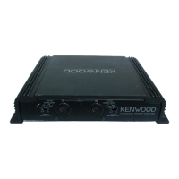
Identifies the fuse, battery, ground, and power control terminals for power supply.
Terminals for connecting speakers, supporting stereo and bridged connections.
Covers LINE IN (RCA) and Speaker Level input terminals for audio signal connection.
Guidance on connecting power, ground, and speaker wires, including safety precautions.
Criteria for selecting speakers based on impedance and input power ratings.
Illustrates how to connect audio sources using RCA cables or speaker level inputs.
Diagrams for stereo and bridged speaker wire connections.
Diagrams showing how to connect the battery wire, control wire, and ground wire.
Example configuration for a 4-channel system with front and rear speakers.
Example configuration for a 2-channel system using bridged connections.
Two examples of connecting 2 channels plus a subwoofer using bridged mode.
Explains frequency band division using coils and capacitors for tri-mode.
Provides a formula and example for calculating crossover frequencies for coils and capacitors.
Important safety notes regarding speaker impedance and component ratings for tri-mode.
Addresses problems like no sound, one-sided sound, or blown fuses with solutions.
Solutions for output levels being too small or too large.
Troubleshooting distorted sound due to wiring, pinching, or incorrect switch settings.
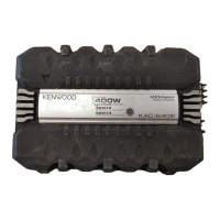
| max power output | 400W |
|---|---|
| rated power output (4Ω, 20Hz~20kHz, 0.08% THD) | 35W x 4 |
| rated power output (4Ω, DIN : 45324, +B=14.4V) | 35W x 4 |
| rated power output (2Ω, 1kHz, 0.8% THD) | 50W x 2 |
| bridged power output (4Ω, 1kHz, 0.8% THD) | 100W x 2 |
| frequency response (+0, -3dB) | 10Hz~45kHz |
| sensitivity (rated output max) | 0.2V |
| sensitivity (rated output min) | 5.0V |
| signal to noise ratio | 100dB |
| input impedance | 10kΩ |
| low pass filter frequency (12dB/oct.) | 50~200Hz (variable) |
| high pass filter frequency (12dB/oct.) | 50~200Hz (variable) |
| RMS watts per channel @ 4Ω < 1% THD+N | 40W x 4 |
| RMS watts per channel @ 2Ω < 1% THD+N | 50W x 4 |
| operating voltage | 14.4V (11~16V allowable) |
|---|---|
| current consumption | 25A |
| dimensions (W x H x D) | 330 x 59 x 242 mm (13 x 2-5/16 x 9-8/16 inch) |
|---|---|
| weight | 3.0kg (6.6 lbs) |