EasyManua.ls Logo

Kenwood KR-A4010 User Manual

Kenwood KR-A4010
36 pages
To Next Page IconTo Next Page
Page #1 background imageLoading...
Page #1 background image
AM/FM
STEREO
RECEIVER
KR-A4010
SERVICE
MANUAL
Panel*
Metallic
cabinet
(A20-)
(A01-1746-01)
KENWOOD
ier
sipcness
rnin
Rasxaord
KENWOOD
©
1989-5
PRINTED
IN
JAPAN
B51-3894-00
(O)
3012
Front
glass
(B10-1006-03)
Phone
jack
Knob
(E11-0162-05)
=
(K27-1987-04)
x
2
Lock
terminal
board
*
Bindinng
post
{E20-)
(NO8-0128-35)
FSot*
Phono
jack
(J02-)
x
4
(E13-0446-05)
Slide
switch
*
($31-2136-05)
Phono
jack
(E13-0621-05)
Knob
(K29-3598-04)
X4
Terminal
board
(E20-0823-05)
AC
outlet*
({E03-)
Slide
switch
(S31-2132-05)
(E30-)
Knob
(K29-3597-04)
Knob
Knob
(K27-1725-04)
(K29-3632-04)
Slide
switch
*
($31-3010-05)
Power
cord
bushing
(J42-0083-05)
AC
power
cord*
*
Refer
to
parts
list
on
page
38.
Question and Answer IconNeed help?

Do you have a question about the Kenwood KR-A4010 and is the answer not in the manual?

Kenwood KR-A4010 Specifications

Audio Specifications IconAudio Specifications
rated power output45 watts per channel
maximum continuous output power45W + 45 W
total harmonic distortion (8 ohms)0.1%
AM Tuner Section IconAM Tuner Section
tuning range530 kHz- 1.610 kHz
usable sensitivity10 pV (320 wV/m)
signal-to-noise ratio50 dB
FM Tuner Section IconFM Tuner Section
tuning frequency range87.5 MHz- 108 MHz
antenna impedance300 ohms balanced & 75 ohms unbalanced
sensitivity (DIN MONO)0.9 pV
Weight and Dimensions IconWeight and Dimensions
weight5.5 kg
width449 mm
height132 mm

Summary

Disassembly for Repair

Block Diagram

Circuit Description

Component and IC Overview

Lists and describes major components and integrated circuits for the receiver.

Microprocessor and Control Logic

Details the microprocessor, port allocation, and user interface logic.

Key ICs: PLL, FM MPX, and Amplifiers

Explains the PLL, FM MPX, and main amplifier integrated circuits.

Adjustment Procedures

FM Section Tuning Adjustments

Procedures for adjusting FM reception parameters like band edge and RF alignment.

AM Section Tuning Adjustments

Procedures for adjusting AM reception parameters like band edge and RF alignment.

Adjustment Setup and Test Equipment

Voltage Table

Schematic Diagram

Exploded View and Parts Identification

Parts List

Technical Specifications

Audio Section Specifications

Details rated power output, frequency response, and distortion for the audio section.

Tuner Section Specifications

Details tuning range, sensitivity, selectivity, and stereo performance for tuners.

General Unit Specifications

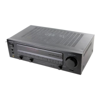
Provides power consumption, physical dimensions, and weight of the unit.

Related product manuals