EasyManua.ls Logo

Kenwood KRX-793 User Manual

Kenwood KRX-793
48 pages
To Next Page IconTo Next Page
Page #1 background imageLoading...
Page #1 background image
STEREO
CASSETTE
RECEIVER
KRX-593/793
SERVICE
MANUAL
KENWOOD
©1993-2
PRINTED
IN
JAPAN
B51-4688-00(MC)
2035
Panel Dressing
plate
tuner
Knob
Dressing
plate
amp
Knob
(A60-0397-01:KRX-793)
{BO3-2838-03)
(K29-5708-02)
(BO3-2839-03)
(K29-4112-03)
(A60-0396-01:KRX-593)
Knob
power
(K29-41
13-04)
Knob
deck
control
(K29-5737-01)
Knob
volume
Knob
x
2
control
(K29-5
738-03)
Knob
b:
MIDBO/AL
TAPE
A
TAPE
B
TUNER
PHONG
co
(K27-2103-04)
(K29-5
709-04)
Phone
jack
{b
j
{
iy
Knob
(E11-0252-05)
L
ar
(K29-5719-04)
ata
a
ae
tee
ae
aa
es
a
el
STEREO
COURLE
CASSETTE
OFC
Dressing
plate
cassette
holder
Dressing
plate
cassette
holder
(BO3-2835-04) (BO3-2835-04)
Knob
Dressing
plate
deck
Knob
{K29-41
21-03)
(B03-2840-03)
(K29-4-121-03)
Knob
Knob
deck
control
Knob
eject
x
2
Cassette
holder
(B)
(K29-41
20-03)
(K29-5736-01)
(K29-5722-04)
|
(AS3-1408-02)
Cassette
holder
(A)
Knob
(A53-1407-02)
(K29-4120-03)
Note
Refer
to
X-722
service
manual
(B51-4376-00)
or
X-45/85
Photo
is
KRX-793
service
manual!
(B51-4347-00),
if
need
description
about
*
Refer
to
parts
list
on
page
47.
cassette
mechanism.
Question and Answer IconNeed help?

Do you have a question about the Kenwood KRX-793 and is the answer not in the manual?

Kenwood KRX-793 Specifications

General IconGeneral
Power output80 watts per channel into 8Ω (stereo)
Frequency response10Hz to 70kHz
Total harmonic distortion0.03%
Input sensitivity (MM)2.5mV
Signal to noise ratio (line)100dB
Dimensions440 x 143 x 303mm
Weight8.2kg

Summary

ACCESSORIES AND REMOTE CONTROL

System Accessories

Lists included items like antennas, batteries, and AC plug adapter for the system.

Remote Control Layout

Details the buttons and functions of the remote control unit for operating the device.

CONTROLS AND INDICATORS

Tuner Section Controls

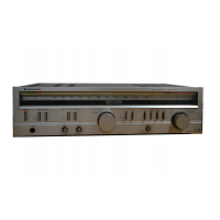
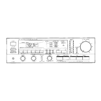
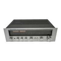
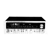
Describes the front panel controls, display, and indicators for the tuner section.

Amplifier & Cassette Deck Controls

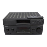
Covers front panel controls, indicators, and input selectors for amplifier and cassette decks.

DISASSEMBLY FOR REPAIR

Front Panel Removal Steps

Provides step-by-step instructions for safely removing the front panel for access.

Internal Component Removal

Details procedures for removing PC boards, chassis, and the rear panel for servicing.

CIRCUIT DESCRIPTION & DIAGNOSTICS

System Block Diagram

Illustrates the overall signal flow and interconnections between major functional blocks.

Receiver & Deck Circuitry

Explains tuner operation, microprocessor, deck functions, and pin assignments.

Operational Timing Charts

Shows timing sequences for power, selector changes, tuning, and other key operations.

ADJUSTMENT PROCEDURES

Tuner Section Adjustments

Details adjustments for FM/AM tuning, discriminator, distortion, and sensitivity.

Cassette Deck Adjustments

Covers demagnetization, cleaning, azimuth, tape speed, bias, and record level adjustments.

DIAGRAMS AND PARTS INFORMATION

Wiring Diagram

Shows the overall internal wiring connections and cable routing of the unit.

Schematic Diagrams

Provides detailed circuit schematics for tuner, display, audio, and power supply sections.

Exploded Views of Unit and Mechanism

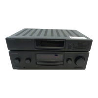
Illustrates the physical assembly of the main unit and the cassette mechanism.

Parts List

Lists all replaceable parts with their part numbers, descriptions, and destination marks.

SPECIFICATIONS

Performance Specifications

Outlines technical performance metrics for amplifier, tuner, and cassette deck sections.

Related product manuals