Do you have a question about the Kenwood NEXEDGE NXR-710 and is the answer not in the manual?
Lists precautions for fire, electric shock, sunlight, dust, humidity, and abnormal odors.
Contains FCC warnings and information regarding RF energy and potential interference.
Details copyrights for embedded firmware and voice coding technology.
Instructions for unpacking the repeater and verifying included parts.
Guidance on attaching handles and seeking dealer assistance for final installation.
Details on connecting a Kenwood microphone to the unit's MIC jack.
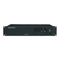
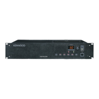
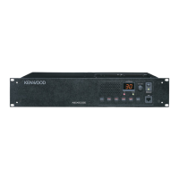
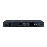
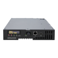
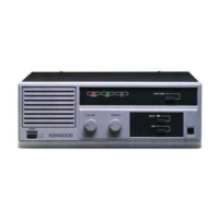
Description of the controls and indicators on the front panel of the repeater.
Description of the connectors and jacks located on the rear panel.
Basic operational steps for the repeater, including power and audio adjustment.
Instructions for receiving and transmitting using the transceiver.
Detailed pin assignment for the 8-pin modular microphone connector.
Detailed pin assignment for the test and external speaker connector.
Detailed pin assignment for the 25-pin D-SUB control interface connector.
Detailed pin assignment for the N-SYNC connectors (RS-485).
Essential safety instructions for installers and users regarding antenna placement and RF exposure limits.
Warning against substituting the supplied or recommended antenna due to radiation risks.