EasyManua.ls Logo

Kenwood NXR-810 Service Manual

Kenwood NXR-810
169 pages
To Next Page IconTo Next Page
Page #1 background imageLoading...
Page #1 background image
SERVICE MANUAL /
维修手册
This product uses Lead Free solder.
无铅焊接通信产品
保护环境建伍领先
注意∶本产品是无铅化焊接产品
在维修时请使用无铅焊锡
和相应的焊接工具
详细事项请访问如下网址了解:
http://www.kenwoodhk.com.hk/
This product complies with the
RoHS
directive for the European market.
© 2010-5 PRINTED IN CHINA
B51-8924-00
(
N
)
C version / C
版本
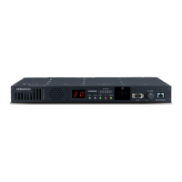
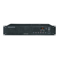
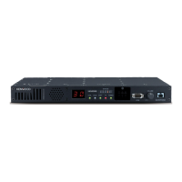
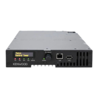
NXR-810
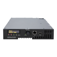
UHF DIGITAL BASE-REPEATER / UHF
数字模拟双模中继台
CH/STATUS
VOLUME
BUSY
TX
POWER
MIC
FUSE
N SYNC
DC 13.6V
REF IN RX IN
TX OUT
CONTROL
I/O
TEST/SPKR
Front panel
前面板
(A62-1174-03)
Knob (Power)
旋钮(电源)
(K29-9106-04)
Key top / 按键
(K29-9370-02)
Knob (Volume)
旋钮(音量)
(K29-5389-03)
Modular jack
模块化插孔
(E58-0522-05)
Rear panel
后面板
(A82-0077-02)
Antenna cable (REF IN)
天线电缆(基准输入)
(E30-7690-05)
Antenna cable (RX IN)
天线电缆(接收输入)
(E30-3418-15)
Lead wire with connector
(ACC15P)
带有连接器的导线(ACC15P)
(E37-0913-05)
Lead wire with connector
(DSUB25P)
带有连接器的导线(DSUB25P)
(E37-1376-05)
Modular jack x 2
模块化插孔 x 2
(E58-0533-05)
DC cord (Ext DC in)
直流电源线(外部直流输入)
(E30-3414-05)
Blade fuse (15A/32V)
刀片式保险丝(15A/32V)
(F05-1537-05)
Antenna cable (TX OUT)
天线电缆(发射输出)
(E30-7528-15)
Question and Answer IconNeed help?

Do you have a question about the Kenwood NXR-810 and is the answer not in the manual?

Kenwood NXR-810 Specifications

General IconGeneral
BrandKenwood
ModelNXR-810
CategoryRepeater
LanguageEnglish

Summary

INTRODUCTION

PERSONAL SAFETY

Crucial safety precautions to follow during operation and maintenance.

REALIGNMENT / MODES

1. Modes

Lists and describes the different operating modes of the device.

3. PC Mode

Details the procedure for operating and configuring the unit via PC.

REALIGNMENT / FIRMWARE PROGRAMMING MODE

4. Firmware Programming Mode

Details the process for upgrading the device's firmware.

OPERATING FEATURES

1. Two 7-segment LED Displays

Explains the function and meaning of the unit's 7-segment LED displays.

INSTALLATION / INSTALLATION

1. External Speaker (KES-5)

Information on connecting the KES-5 external speaker.

DISASSEMBLY FOR REPAIR / REPAIR DISASSEMBLY

1. How to Remove the Panel Assy (ABS)

Step-by-step guide for removing the unit's panel assembly.

CIRCUIT DESCRIPTION / CIRCUIT DESCRIPTION

2. TX-RX unit / 2. TX-RX unit

Detailed description of the circuits within the TX-RX unit.

2-1. Internal/External reference circuit / 2-1. Internal/External reference circuit

Explanation of the internal and external reference signal circuits.

CIRCUIT DESCRIPTION / CIRCUIT DESCRIPTION

3. Final unit / 3. Final unit

Description of the final unit, including its sub-circuits.

3-4. APC circuit / 3-4. APC circuit

Explanation of the automatic transmission power control circuit.

CIRCUIT DESCRIPTION / CIRCUIT DESCRIPTION

4-5. Power supply circuit / 4-5. Power supply circuit

Detailed description of the unit's power supply circuits.

COMPONENTS DESCRIPTION / COMPONENT DESCRIPTION

FINAL UNIT (X45-3932-71) / FINAL UNIT (X45-3932-71)

Lists and describes the components of the Final Unit.

PARTS LIST / PARTS LIST

FINAL UNIT (X45-3932-71) / FINAL UNIT (X45-3932-71)

Comprehensive list of parts for the Final Unit.

TROUBLE SHOOTING / TROUBLESHOOTING

● Checking power supply voltage / ● Checking power supply voltage

Procedures for checking power supply voltages to diagnose faults.

TROUBLE SHOOTING / TROUBLESHOOTING

The display indicates “E 3 ” / The display indicates “E 3 ”

Explains the meaning and potential causes of the "E 3" error display.

ADJUSTMENT / ADJUSTMENT

Test Equipment Required for Alignment / Test Equipment Required for Alignment

Lists the necessary test equipment for unit alignment procedures.

ADJUSTMENT / ADJUSTMENT

Common Section / Common Section

Describes common adjustment procedures applicable to multiple modes.

TERMINAL FUNCTION / TERMINAL FUNCTION

Final Unit (X45-3932-71) (A/3) / Final Unit (X45-3932-71) (A/3)

Details the pin functions for the Final Unit (A/3) connector.

TX-RX Unit (X57-7952-71) / TX-RX Unit (X57-7952-71)

Details the pin functions for the TX-RX Unit connector.

NXR-810 PC BOARD / PC板

NXR-810 SCHEMATIC DIAGRAM / 原理图

FINAL UNIT (X45-3932-71) (A/3) / FINAL UNIT (X45-3932-71) (A/3)

Schematic diagram for the Final Unit (A/3) circuit.

CONTROL UNIT (X53-4490-10) / CONTROL UNIT (X53-4490-10)

Schematic diagram for the Control Unit circuit.

NXR-810 BLOCK DIAGRAM / 方块图

CONTROL UNIT (X53-449) / CONTROL UNIT (X53-449)

Block diagram showing the Control Unit's main functional blocks.

OPTIONAL ACCESSORIES / 可选附件

KES-5 (EXTERNAL SPEAKER / 外部扬声器) / KES-5 (EXTERNAL SPEAKER / 外部扬声器)

Details and specifications for the KES-5 external speaker.

SPECIFICATIONS / 规格

General / 概 述

General technical specifications of the NXR-810 unit.

Receiver / 接 收

Technical specifications related to the receiver section.

Transmitter / 发 射

Technical specifications related to the transmitter section.
Related product manuals