EasyManua.ls Logo

Kenwood NXR-800 - User Manual

Kenwood NXR-800
199 pages
Print Icon
To Next Page IconTo Next Page
Loading...
SERVICE MANUAL
This product complies with the
RoHS
directive for the European market.
This product uses Lead Free solder.
© 2014-4 PRINTED IN JAPAN
RQ022
(K)
B5B-7118-00
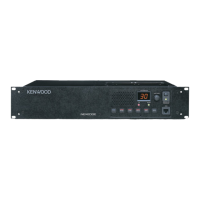
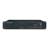
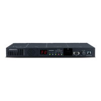
UHF DIGITAL BASE-REPEATER
NXR-800
Badge
(B43-1188-04)
Main panel
(A62-1142-02)
Knob (VOL)
(K29-4539-04)
Lead wire with
connector (DSUB-9P)
(E37-1311-05)
Lead wire with
connector (DSUB-25P)
(E37-1310-05)
Lead wire with
connector (BNC-RX)
(E37-1303-05)
Lead wire with
connector (ACC15)
(E37-1313-05)
Lead wire with
connector (BNC-REF.)
(E37-1304-05)x2
Modular jack
(E58-0526-05)
RF coaxial
receptacle (BNC)
(E04-0463-05)
Fanmotor
(F09-0488-15)
DC cord
(E30-7581-05)
Blade fuse
(F05-7521-05)
Cover (Fan)
(F07-1930-05)
Modular jack
(E58-0516-05)
Modular jack
(E58-0533-05)x2
DC 13.8V
75
CONTENTS
GENERAL .......................................................... 2
SYSTEM SET-UP ............................................... 3
REALIGNMENT ................................................. 3
OPERATING FEATURES .................................. 5
INSTALLATION .................................................. 6
CIRCUIT DESCRIPTION ................................... 8
COMPONENTS DESCRIPTION ...................... 24
TERMINAL FUNCTION ................................... 28
PARTS LIST ..................................................... 42
EXPLODED VIEW ............................................ 76
PACKING ......................................................... 78
TROUBLE SHOOTING .................................... 79
ADJUSTMENT ................................................. 87
PC BOARD..................................................... 100
SCHEMATIC DIAGRAM ................................ 124
OPTIONAL ACCESSORIES .......................... 140
SPECIFICATIONS .......................................... 143
APPENDIX 1 (BLOCK DIAGRAM)
APPENDIX 2 (INTERCONNECTION DIAGRAM)
APPENDIX 3 (SCHEMATIC DIAGRAM X53-413)
APPENDIX 4 (SCHEMATIC DIAGRAM X53-414)
K5 version

Other manuals for Kenwood NXR-800

Questions and Answers

  • S
    Selena VasquezAug 16, 2025
    What does it mean if the clock oscillation amplitude is weak in Kenwood NXR-800?
    • R
      renee64Aug 16, 2025
      If the clock oscillation amplitude is weak, it suggests the drive circuit in IC34 of your Kenwood Repeater is malfunctioning.
  • K
    Kevin BrownAug 19, 2025
    What does it mean if clock oscillation amplitude is weak for IC324 in Kenwood NXR-800 Repeater?
    • S
      Sandra BellAug 19, 2025
      If the clock oscillation amplitude is weak, it indicates that the drive circuit for IC324 in your Kenwood Repeater is malfunctioning.
  • R
    Robert ButlerAug 21, 2025
    What does it mean if IC34 shows 5 VDC in Kenwood NXR-800?
    • C
      cassieortegaAug 21, 2025
      If the voltage measures 5 VDC, then IC34 in your Kenwood Repeater is malfunctioning.
  • Z
    zmoonAug 25, 2025
    What does it mean if IC703 reads 3.3VDC in Kenwood Repeater?
    • M
      marquezmonicaAug 25, 2025
      If the voltage is 3.3VDC, IC703 in your Kenwood Repeater is malfunctioning.
  • M
    Meghan ShahAug 27, 2025
    What does it mean if IC703 reads 1.5VDC in Kenwood NXR-800 Repeater?
    • K
      Kenneth MendezAug 27, 2025
      If the voltage is 1.5VDC, IC703 in your Kenwood Repeater is malfunctioning.
  • I
    Ian BennettAug 30, 2025
    What does it mean if the output voltage is 1.5VDC for IC324 in Kenwood NXR-800 Repeater?
    • J
      jennifer32Aug 30, 2025
      If the output voltage is 1.5VDC, IC324 in your Kenwood Repeater is malfunctioning.
  • K
    Kelly WilliamsSep 3, 2025
    What does it mean if IC708 is not 3.3VDC in Kenwood Repeater?
    • K
      Kimberly LopezSep 3, 2025
      If the voltage is not 3.3VDC, IC708 in your Kenwood Repeater is malfunctioning.
  • J
    Jeanette LongSep 5, 2025
    What does it mean if IC314 reads 3.3VDC in Kenwood NXR-800?
    • C
      codycarlsonSep 5, 2025
      If the voltage is 3.3VDC, IC314 in your Kenwood Repeater is malfunctioning.
  • C
    Caitlyn PowellSep 8, 2025
    What does it mean if IC303 is equal to or less than 3.3VDC in Kenwood NXR-800?
    • C
      Connie PowersSep 9, 2025
      If the voltage is equal to or less than 3.3VDC, IC303 in your Kenwood Repeater is malfunctioning.
  • D
    David KnightSep 12, 2025
    What does it mean if IC325 is not 3.3VDC in Kenwood NXR-800?
    • D
      Deborah AdamsSep 12, 2025
      If the voltage is not 3.3VDC, IC325 in your Kenwood Repeater is malfunctioning.

Summary

General Information

Personal Safety Precautions

Lists essential safety guidelines for operating the equipment, including antenna proximity and grounding.

Service Information

Provides general information on servicing the transceiver and refers to relevant sections for detailed procedures.

System Set-Up

PC Mode

Covers the preface and connection procedure for programming the NXR-800 via PC.

Realignment

PC Programming and Firmware Update

Details PC connection, firmware programming steps, and cable specifications for the NXR-800.

Operating Features

Installation

OCXO (KXK-3) Installation

Details the mounting and connection of the KXK-3 OCXO unit.

External Speaker (KES-5) Connection

Provides step-by-step instructions for connecting the KES-5 external speaker, including terminal manipulation.

Circuit Description

Transmitter Unit Circuits

Details the internal/external reference, 19.2MHz PLL reference, modulation PLL, DDS, and main PLL circuits of the transmitter unit.

Terminal Function

Trouble Shooting

Adjustment

Alignment Procedures

Details the step-by-step alignment procedures for various NXR-800 parameters, including VCO lock voltage and deviation.

Specifications

Kenwood NXR-800 Specifications

General IconGeneral
Digital ProtocolNXDN
Operating Voltage13.6 V DC
Modulation16K0F3E
Frequency Range136-174 MHz, 400-520 MHz
Dimensions19 x 1.75 x 13.78 in (483 x 44 x 350 mm)

Related product manuals