NXR-800
14
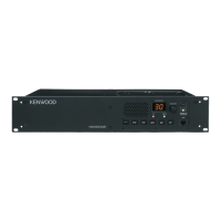
3-7. FAN action control circuit
The FAN action control circuit consists of a FAN, a cur-
rent detection resistance (R11), a Differential amplifier
(IC15), a Switching FET (Q3), and a Switching FET (Q14).
It detects the normal and abnormal state by monitoring the
current fl owing FAN motor, and stops operation when failure
occurs.
Fig. 13 FAN action control circuit
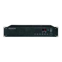
3-8. Current detector circuit
The current detector circuit monitors the current of the
Power Amplifi er Module. It consists of a current detection
resistance (R4) and a current detection IC (IC1). It detects
the normal and abnormal state of the Power Amplifi er Mod-
ule by monitoring the current of the Power Amplifi er Module.
If a failure occurs, it stops operation.
IC1
Current
sense IC
PA_CURR
R4
Fig. 14 Current detector circuit
3-9. AVR circuit
IC3, IC11 and IC12 are AVR ICs.
They maintain isolation of each power supply.
Fig. 15 AVR circuit
3-10. Other circuits
Circuit IC9 saves various adjustment values of the Final
Unit in the EEPROM.
4. Receiver Unit
The receiver unit (X55-310) consists of the following cir-
cuits:
(1) Front-end circuit
(2) 1st-Mixer circuit
(3) 1st-IF circuits
(4) Demodulator circuits
(5) Squelch circuit
(6) Receiver DDS circuit
(7) Receiver PLL circuits
(8) AVR circuit
(9) Other circuits
There are fi ve modulating modes that can receiver de-
modulate, including Analog_Wide, Analog_Narrow, NXDN_
Narrow, and NXDN_Very-Narrow.
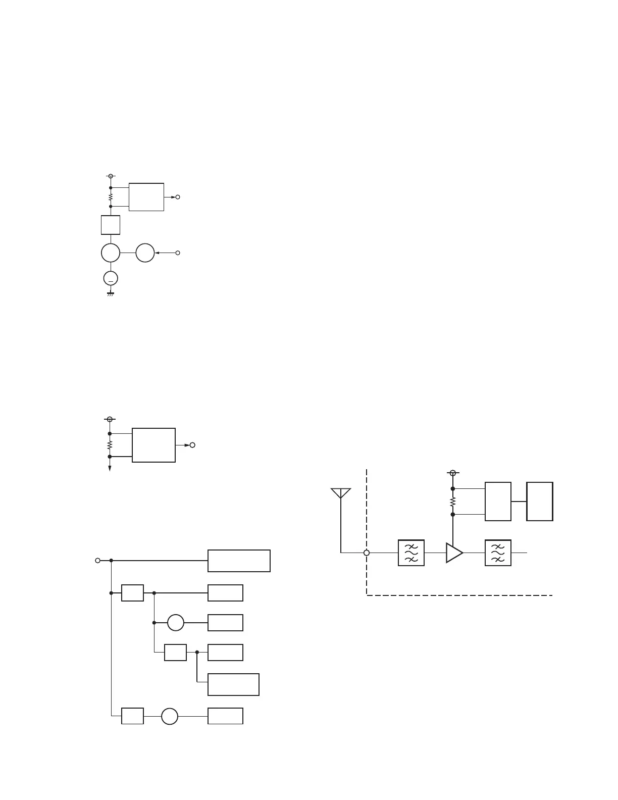
4-1. Front-end circuit
The front-end circuit consists of L132 and L133 helical
BPF, Q1 Low Noise Amplifi er (LNA), and L134 and L135 he-
lical BPF. Adjusting four helical BPF forms the BPF having a
pass band width of 5MHz with a center frequency from 368
to 400MHz.
+9V is applied to the Q1 collector power supply. The col-
lector current is monitored by the IC4 current detection cir-
cuit. Detected DC voltage is input to pin 15 of IC30 (ADC).
Fig. 16 Front-end circuit
CIRCUIT DESCRIPTION
Q3
SW
M
Q14
SW
IC12
AVR
IC15
Diff. AMP
FAN_CURR
FAN_CONT
VBATT
R11
+8V
IC11
+5V
IC12
+5V OP AMP
OP AMP
IC3
SW
Q4,5
ANT SW
Temp
protection IC
FAN
Power amplifier
module
CN2
+VBATT
IC2,4,5,8
IC10
IC6
IC7
SW
Q3,14
BPF
L132, 133
BPF
L134, 135
Q1
LNA
IC4
IC30
+9V
15
RX ANT
CN5
RX unit
X55-310

 Loading...