NXR-800
5
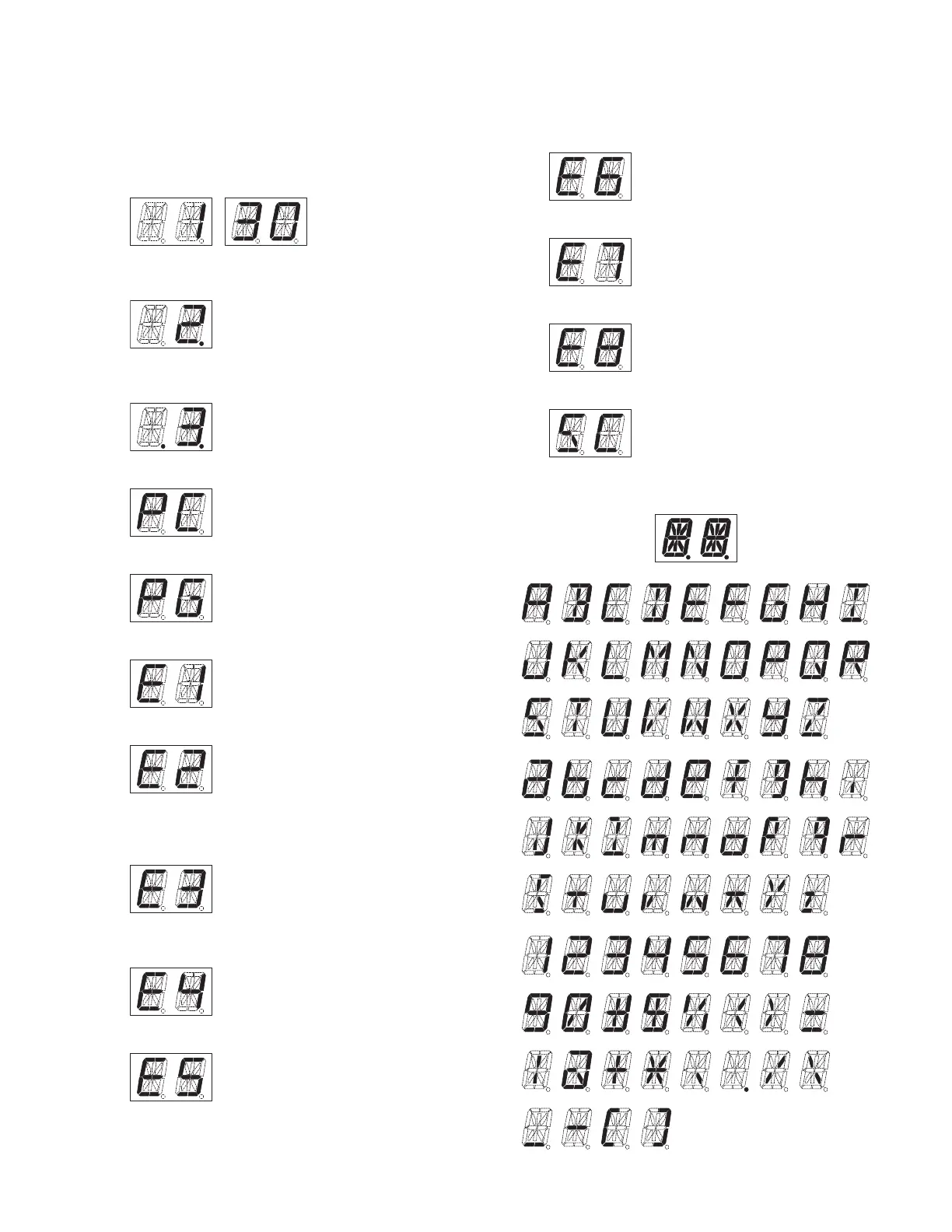
1. Two 17-segment LED Displays
• Channel display (1~30): While operating normally in user
mode.
• When the displayed channel is contained in scan se-
quence, the right side decimal point is displayed.
• When the displayed channel is the priority channel, the
left side decimal point is displayed.
• “PC” is displayed while in PC mode.
• “PG” is displayed while in fi rmware programming mode.
• “E1” is displayed when FPU data is not written.
• “E2” is displayed when the channel data is not written.
• “E3” is displayed when PLL is unlocked.
Receiver PLL unlocked = BUSY LED blinks.
Transmitter PLL unlocked = TX LED blinks.
• “E4” is displayed when PTT is attempted on a channel
number that has no frequency data programmed.
• “E5” is displayed when IP address confi guration is error.
A
All segments ON
BCDEFGHI
JKLMNOPQR
STUVWXYZ
abcdef gh i
jklmnopqr
stuvwxyz
12345678
90#$%( )=
|@+ ,./\
_- [ ]
OPERATING FEATURES
• “E6” is displayed when no frame clock is entered.
• “E7” is displayed when the thermal protection occurs.
• “E8” is displayed when Failure Input port becomes active.
• “SC” is displayed while in scan mode.

 Loading...