SERVICE MANUAL
This product uses Lead Free solder.
This product complies with the
RoHS
directive for the European market.
© 2009-12 PRINTED IN JA PAN
B51-8901-00
(
N
)
527
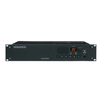
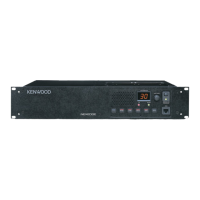
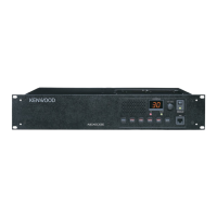
NXR-710
VHF DIGITAL BASE-REPEATER
CH/STATUS
VOLUME
BUSY
TX
POWER
MIC
FUSE
N SYNC
DC 13.6V
REF IN RX IN
TX OUT
CONTROL
I/O
TEST/SPKR
Front panel
(A62-1174-03)
Knob (Power)
(K29-9106-04)
Key top
(K29-9370-02)
Knob (Volume)
(K29-5389-03)
Modular jack
(E58-0522-05)
Rear panel
(A82-0077-02)
Antenna cable (REF IN)
(E30-7690-05)
Antenna cable (RX IN)
(E30-3418-15)
Lead wire with connector
(ACC15P)
(E37-0913-05)
Lead wire with connector
(DSUB25P)
(E37-1376-05)
Modular jack x 2
(E58-0533-05)
DC cord (Ext DC in)
(E30-3414-05)
Blade fuse (15A/32V)
(F05-1537-05)
Antenna cable (TX OUT)
(E30-7528-15)
GENERAL ................................................................... 2
SYSTEM SET-UP ....................................................... 3
REALIGNMENT ......................................................... 3
OPERATING FEATURES ........................................... 5
INSTALLATION .......................................................... 6
MODIFICATION ......................................................... 8
DISASSEMBLY FOR REPAIR .................................... 8
CIRCUIT DESCRIPTION ............................................ 9
COMPONENTS DESCRIPTION ............................... 18
PARTS LIST ............................................................. 20
EXPLODED VIEW .................................................... 36
PACKING .................................................................. 38
ADJUSTMENT ........................................................ 39
TERMINAL FUNCTION ........................................... 53
PC BOARD
FINAL UNIT (X45-3920-10) ................................. 58
CONTROL UNIT (X53-4490-10) .......................... 62
DISPLAY UNIT (X54-3580-20) ............................. 66
TX-RX UNIT (X57-7940-10) ................................. 70
RX VCO/PLL UNIT (X58-5070-10) ...................... 74
TX VCO/PLL UNIT (X58-5080-10) ...................... 75
INTERCONNECTION DIAGRAM ............................ 76
SCHEMATIC DIAGRAM .......................................... 78
BLOCK DIAGRAM ................................................... 96
OPTIONAL ACCESSORIES
KES-5 (EXTERNAL SPEAKER) ............................ 99
SPECIFICATIONS ................................. BACK COVER
CONTENTS